Parameter descriptions
7.6.5 Digital outputs
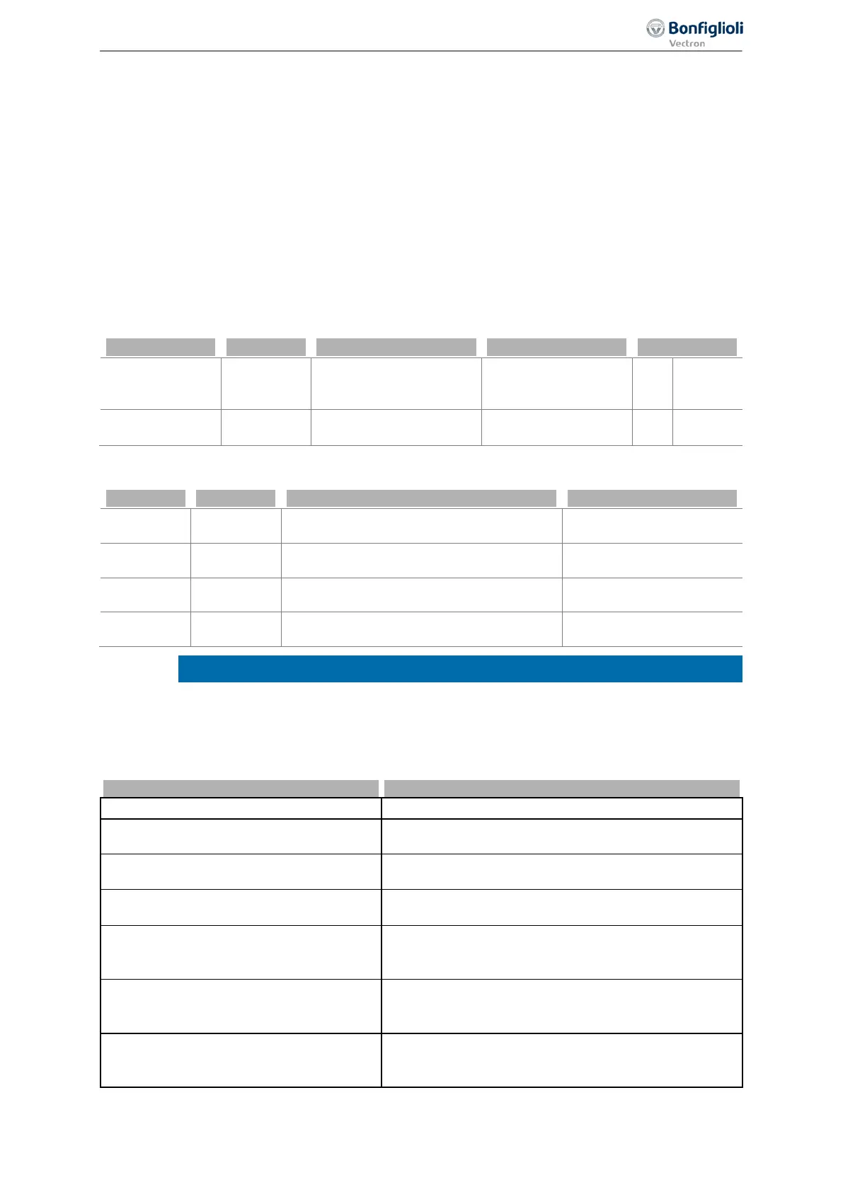
531 Operation Mode OUT1D (X13.5) (Digital output)
532 Operation Mode OUT2D (X10/relay)
533 Operation Mode OUT3D (X11.6) (Digital input/output)
554 Digital: Source MFO1D (Multifunction output)
The digital signals listed in table "Operation modes for digital outputs" can be output via:
− Digital output
− Multifunction output (set as digital output)
− Digital input/output (set as digital output)
− Relay output
If the multifunction output or digital input/output is to output a digital value, the relevant output must
be set up as a digital output:
Multifunction
output
X13.6
Operation Mode MFO1
(X13.6)
550
10 -
(PWM)
1 -
Digital
MFO1D
put/output
X11.6
Operation Mode Termi-
nal X11.6 558
0 - Input IN3D 1 -
OUT3D
Factory settings of digital outputs
Output Terminal Parameters Factory setting
X13.5
Operation Mode OUT1D (X13.5) 531
2 - Run signal
X13.6
Digital: Source MFO1D 554
4 - Setting frequency
X11.6
Operation Mode OUT3D (X11.6) 533
103 - Inv. error signal
X10
Operation Mode OUT2D (X10/relay) 532
103 - Inv. error signal
The relay output at terminal X10 is switched off if the communication between control
and power circuitry of the frequency inverter is
faulty. This avoids dangerous conditions
for example in the brake control of hoist applications.
Operation modes for digital outputs
Operation mode 531, 532, 533, 554
0 -
Off Digital output is switched off
1 -
Ready or Standby Signal
Frequency inverter is initialized and on stand-by or in
operation
2 -
Run Signal
Enable signals STOA and STOB and a start command
are present, output frequency available.
3 -
Error Signal
The message is displayed via parameter Actual error
259.
4 -
Setting Frequency
The Stator frequency 210 is higher than the parameter-
ized Setting frequency 510. See chapter 7.6.5.2
5 -
Reference Frequency reached
The Actual frequency 241 of the drive has reached the
Internal reference frequency 228. See chapter 7.6.5.3
"Reference value reached".
6 -
Reference Percentage reached
The Actual percentage 230 has reached the Reference
percentage 229. See chapter 7.6.5.3 "Reference value
187
Control inputs and outputs 06/2013 Operating Instructions
Agile

 Loading...


