Parameter descriptions
21 -
RF Double Evaluation
Repetition frequency input at digital input IN2D (at terminal
X11.5). Both edges of the frequency signal are evaluated. The
signal can also be evaluated as a percentage. See
7.6.7.2
“Repetition frequency input”.
30 -
Pulse Train
Pulse train (pulse sequence) signal at digital input IN2D (at ter-
minal X11.5) as reference frequency. Via parameter Pulse Train
Scaling Frequency
654, you can set which input frequency cor-
responds to the value of
Maximum Frequency 419. See 7.6.7.3
“Pulse train”.
Percentage: Via parameter Pulse Train Scaling Frequency 654,
you can set which percentage corresponds to the value of
Maxi-
mum Reference Percentage
519. The signal can also be evaluat-
Digital input IN2D is intended for use as PWM input, repetition frequency input or
pulse train input. Digital input IN2D cannot be used for other functions if the function
PWM input, repetition frequency or pulse train is selected for
496.
In the factory settings, IN2D is linked to parameter
Start Anticlockwise 69
. If the
PWM, repetition frequency or pulse train input and the function "Start anticlockwise"
are to be used parameter
Start Anticlockwise 69
must be assigned another digital
input.
7.6.7.1 PWM input
Digital input IN2D (terminal X11.5) can be used as PWM input. For parameter Operation Mode
IN2D
496, select setting "10 - PWM, 0% –100%" or "11 – PWM, -100% – 100%".
For definition of reference values, the following settings can be selected:
−
Reference Percentage Source 1 476 = "10 - Repetition Percentage Value".
−
Reference Percentage Source 2 494 = "10 - Repetition Percentage Value".
The percentage is referred to
Maximum Reference Percentage 519.
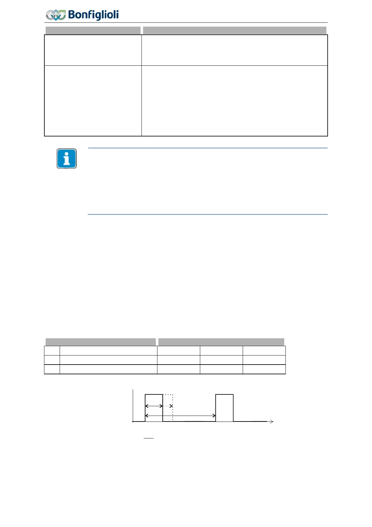
652 PWM-Offset
653 PWM-Amplification
Via parameters PWM-Offset 652 and PWM-Amplification 653, the PWM input signal can be adjusted
for the application.
[ ]
×+= 653652 %
T
T
valuePWM
on
ionAmplificat-PWMOffsetPWM
-
PWM-Input 258 shows the actual value of the PWM input.
PWM frequencies in the range between 50 Hz and 15 kHz can be evaluated.
208
Operating Instructions
Agile
06/2013 Control inputs and outputs

 Loading...


