Parameter descriptions
7.10.4.1 Dimensioning of brake resistor
WARNUNG
Connect a brake resistor following the instructions and safety information provided in
chapter 5.6.5 “Brake resistor”.
The following values must be known for dimensioning:
− Peak braking power P
b Peak
in W
− Resistance R
b
in Ω
− Relative operation time OT in %
• Calculation of peak braking power P
b Peak
( )
b
2
2
2
1
Peak b
t182
nnJ
P
⋅
−⋅
=
Moment of inertia of drive system in kgm
2
1
Speed of drive system before the braking operation in
min
-1
2
Speed of drive system after the braking operation in
min
-1
• Calculation of resistance R
b
The switch-on threshold U
d BC
is the DC link voltage at which the brake resistor is switched on. The
switch-on threshold can be set via parameter
Trigger Threshold 506.
CAUTION
The resistance of the brake resistor must not be less than the minimum value R
b min
-
10%. The values for R
b min
are listed in chapter 11 "Technical data".
If the calculated resistance R
b
of the brake resistor is between two standard series values, the lower
resistance must be selected.
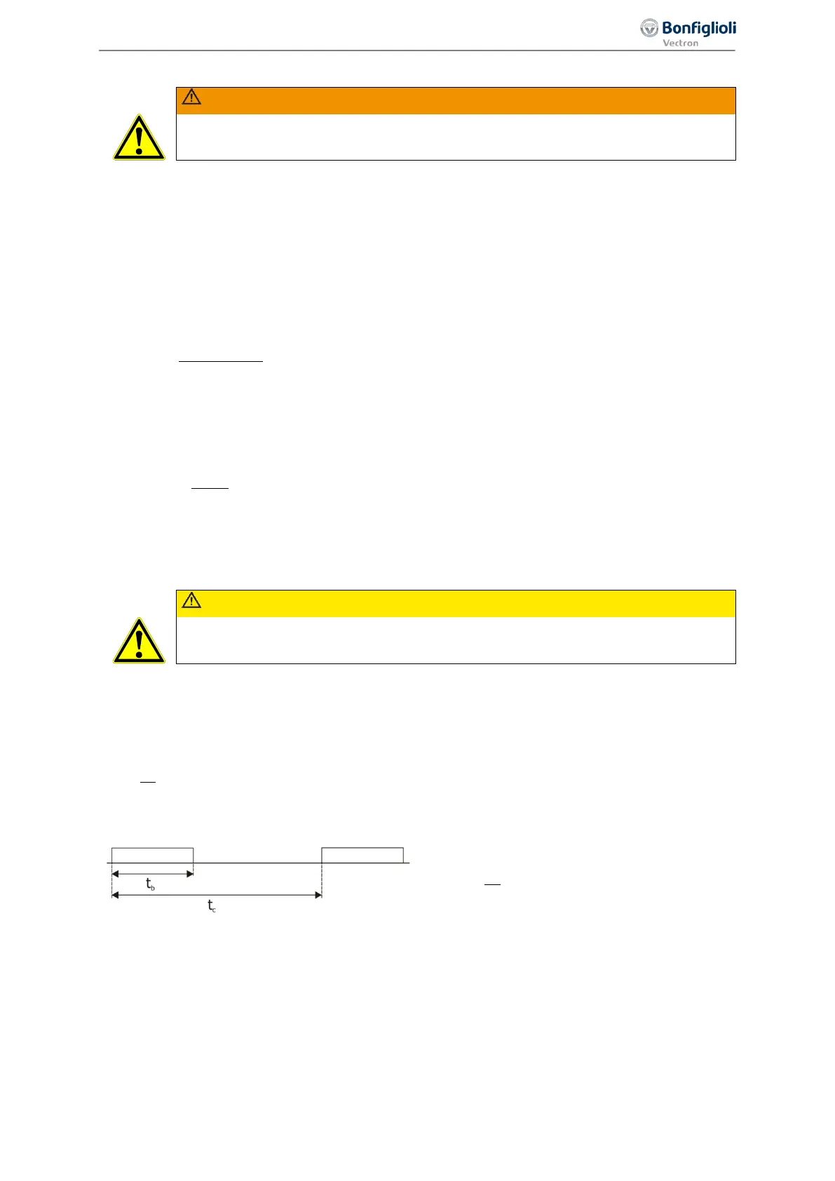
• Calculation of relative operation time OT
Relative operation time (percentage duty cycle)
Braking time (duty cycle)
In the case of infrequent short braking operations, typical values of the relative operation time OT are
at 10%, for long braking operations (≥ 120 s) typical values are at 100%. In the case of frequent
deceleration and acceleration operations, it is recommended that the relative operating time OT be
calculated according to the above formula.
The calculated values for P
b Peal
, R
b
and OT can be used by the resistor manufacturers for determining
the resistor-specific permanent power.
243
Special functions 06/2013 Operating Instructions
Agile

 Loading...


