Parameter descriptions
7.4.2 Temperature
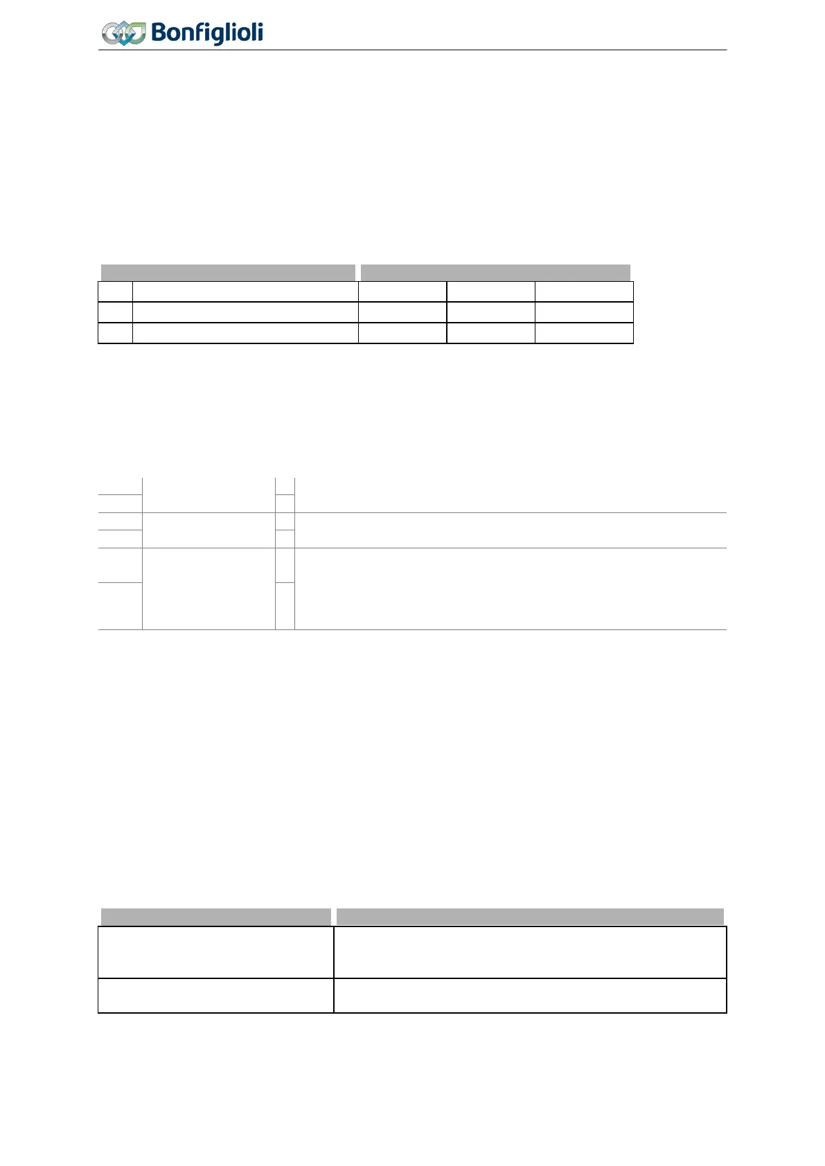
407 Warning limit heat sink temp.
408 Warning limit inside temp.
The ambient conditions and the energy dissipation at the current operating point result in the fre-
quency inverter heating up. In order to avoid an error switch-off of the frequency inverter, the
Warn-
ing limit heat sink temp.
407 for the heat sink temperature limit and the Warning limit inside temp.
408 as an internal temperature limit are to be parameterized. The temperature value at which a
warning message is output is calculated from the type-dependent temperature limit minus the adjust-
ed warning limit.
The switch-off limit of the frequency inverter is dependent of the construction size.
407 Warning limit heat sink temp. -25 °C 0 °C -5 °C
408 Warning limit inside temp. -25 °C 0 °C -5 °C
The exceeding of the maximum permissible internal temperature is signaled if the sensor for internal
temperature or the sensor for the electrolytic capacitor temperature measures the type-specific limit
value. For internal temperature and electrolytic capacitor temperature different limits are defined.
Output signals
Reaching of warning limits is reported via digital signals.
Heat sink tempera-
ture warning
The value "temperature limit minus Warning limit heat sink
temp.
407" was reached.
Inside temperature
warning
The value "temperature limit minus Warning limit inside temp. 408"
was reached.
170 -
Warning over-
temperature
1)
− "temperature limit minus Warning limit heat sink temp. 407" or
− "temperature limit minus
Warning limit inside temp. 408"
12 -
2)
1)
For linking to frequency inverter functions.
2)
For output via a digital output. Select the signal source for one of the parameters 531, 532, 533,
554. See chapter 7.6.5 "Digital outputs".
7.4.3 Controller status
409 Controller-Status Message
Intervention by a controller can be displayed via the operator panel. The selected control methods
and the matching monitoring functions prevent a switch-off of the frequency inverter. The interven-
tion of the function changes the operating behavior of the application and can be displayed by the
status messages with parameter
Controller status 275. The limit values and events which result in
the intervention by the corresponding controller are described in the corresponding chapters. The
behavior during the intervention of a controller is configured with the parameter
Controller-Status
Message
409.
Controller-Status Message 409
0 - No Message
The intervention of a controller is not reported.
The controllers influencing the operating behavior are dis-
played in the
275 parameter.
1 – Warning Status
The limitation by a controller is displayed as a warning by the
operator panel.
Chapter 7.6.5.8 "Warning mask" contains a list of controllers and describes further ways for evaluating
the controller states.
136
Operating Instructions
Agile
06/2013 Error and warning behavior

 Loading...


