Parameter descriptions
• Set parameters Acceleration (Clockwise) 420 and Deceleration (Clockwise) 421 or Acceleration
Anticlockwise
422 and Deceleration Anticlockwise 423 to the required values. For synchronous
acceleration and deceleration of the drives, set the values of the slave drive slightly higher (in ex-
ample 10 %) than the values of the master drive. These increased values are to ensure that the
slave drive can follow the master drive in dynamic operation cases.
• For a synchronous start of the master drive and the slave drive, set the
Minimum Frequency 418
of the slave drive to 0 in order to prevent an early start of the slave drive if the controller enable
signal is present.
• Select an
Operation Mode 689. Via parameters Gear Factor Numerator 685 and Gear Factor
Denominator
686, set the required transmission ratio.
WARNING
In order to avoid time delays during the processing of the repetition frequency, the
slave frequency inverter should be enabled before the master frequency inverter.
WARNING
The reference frequency is transmitted, but not the direction of rotation. In this case,
the direction of rotation must be defined via the digital inputs IN1D and IN2D at the
slave drive.
7.6 Control inputs and outputs
The control inputs and outputs can be parameterized freely. All hardware inputs and outputs are pre-
set to frequently used functions by default for simple commissioning.
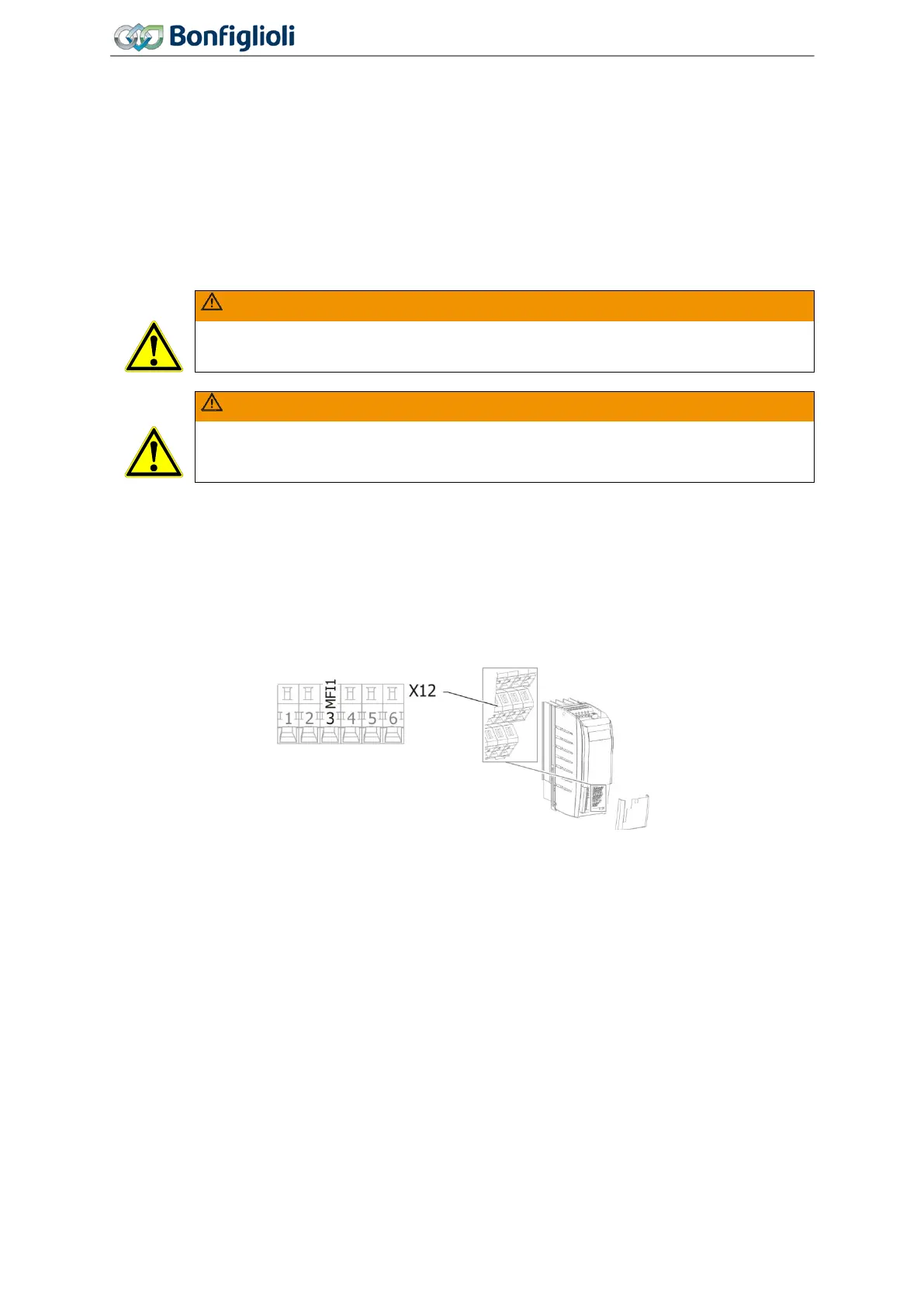
7.6.1 Multifunction input MFI1
452 Operation Mode MFI1 (Multifunction input 1)
Multifunction input MFI1 can be configured as a voltage, current or a digital input. In the configuration
as a digital input, the evaluation can be selected as PNP (high-switching) or NPN (low-switching).
Depending on the selected
Operation Mode MFI1 452, various functions of the frequency inverter
can be controlled.
168
Operating Instructions
Agile
06/2013 Control inputs and outputs

 Loading...


