Options
12.9.2.3 Additional fan or liquid cooling
The size of the heat sink can be reduced if fans are installed or a liquid cooling system is used in addi-
tion to the "Cold Plate" assembly.
The size of the external heat sink can be reduced proportionally to the increase in the flow rate of the
cooling medium.
In the following a fan cooling system is described as an example. For calculating the maximum per-
missible heat resistance R
th enforced
for cooling by means of a fan, a proportionality factor is introduced.
This factor describes the increase of the maximum permissible thermal resistance at increasing flow
rate of the cooling air.
The maximum permissible thermal resistance R
th enforced
for enforced air cooling can be calculated as
follows:
R
th
: Maximum permissible thermal resistance with free circulation of air. Calculate according to the
formula for R
th
in the previous chapter or use the value indicated in the table.
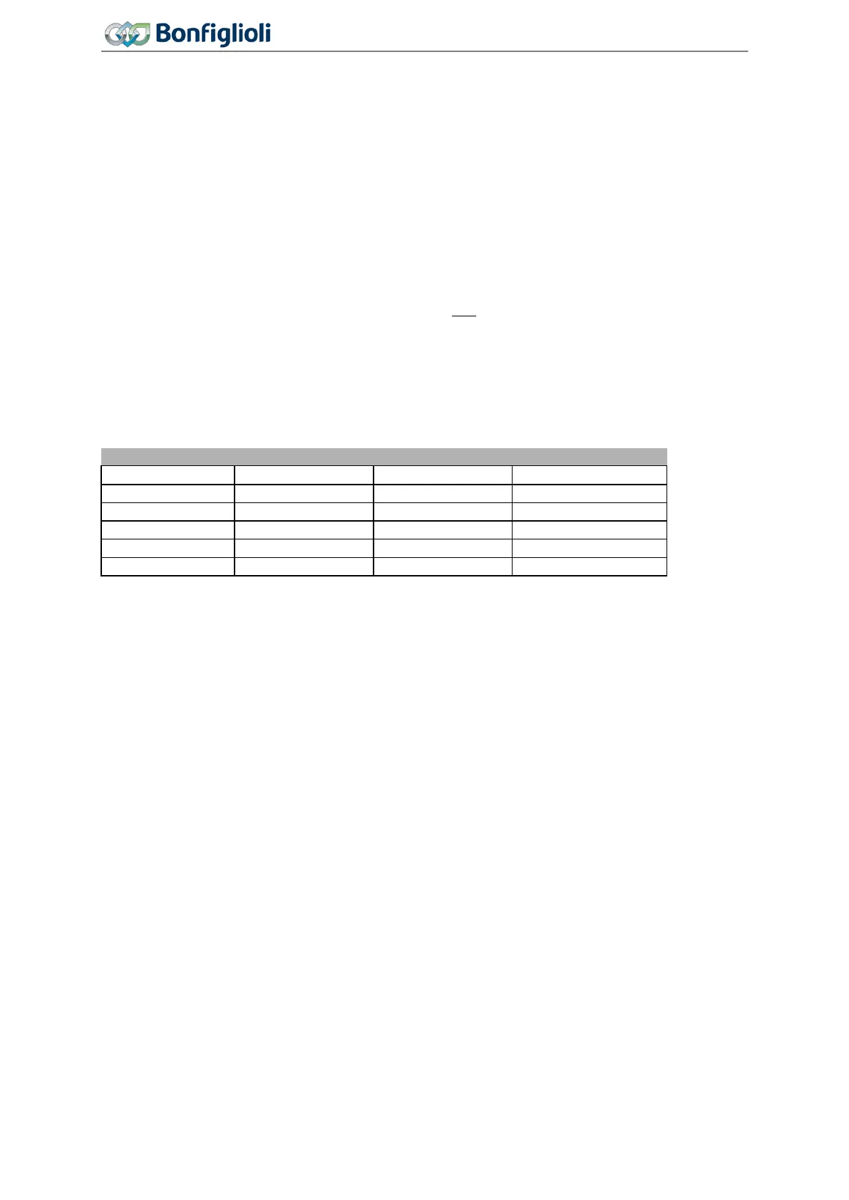
α: Proportionality factor.
The relation is shown, as an example, in the following table for the
Agile
402-23 frequency inverter.
Thermal resistance for enforced air cooling
12.9.2.4 Application notes
− Comply with the operation diagrams for power reductions (derating).
− Comply with the thermal limiting values of the frequency inverter. Refer to chapter 11 “Technical
data” and 12.9.2.4.1 “Temperature monitoring”.
− Additional power losses P
d interior
are dissipated as heat into the interior of a control cabinet. These
losses may amount to 30% of the total energy dissipation and must be considered in the calcula-
tion of the volume of the control cabinet. The values are listed in the tables in chapter 12.9.2.2
“Required thermal properties of the external heat sink”.
− If several frequency inverters or other heat-producing devices are mounted on a common heat sink
(sum cooler), the losses of all devices must be added up. Calculate the maximum permissible
thermal resistance R
th
using the formula (chapter 12.9.2.2 “Required thermal properties of the ex-
ternal heat sink”).
− The contact surface of the external heat sink must have a sufficient thermal conductivity.
12.9.2.4.1 Temperature monitoring
The heat sink temperature and the interior temperature can be monitored:
− The temperatures can be displayed in the actual value menu. Refer to chapter 9.1 “Actual values
of frequency inverter”.
− When the maximum permitted temperatures are reached error-switch-off is effected and an error
message is triggered.
− Before the maximum permitted temperatures are reached a warning message is triggered. An er-
ror-switch-off can be avoided. The temperature values for the warnings can be set via parameter.
Refer to chapter 7.4.2 “Temperature”.
316
Operating Instructions
Agile
06/2013 Assembly variants

 Loading...


