Commissioning
6.2.7 Check direction of rotation
WARNING
The unit may only be connected with the power supply switched off.
Make sure that the frequency inverter is discharged.
Dangerous voltage may be present at the motor terminals and the terminals of the
brake resistor even after the frequency inverter has been disconnected from power sup-
ply. Wait for some minutes until the DC link capacitors have discharged before
to work at the unit.
To check if the reference value and the actual direction of rotation of the drive correspond to one
another, proceed as follows:
• Operate the drive at low speed, i.e. specify a reference value of approx. 10%.
• Switch on frequency inverter enable briefly:
signal at digital inputs STOA and STOB as well as IN1D (Start clockwise) or
signal at digital inputs STOA and STOB as well as IN2D (Start anticlockwise).
• Check if the motor shaft turns in the required direction.
In case the sense of rotation is wrong, exchange two motor phases, e.g. U and V at the terminals of
the frequency inverter. The mains-side connection of the frequency inverter does not affect the sense
of rotation of the drive. In addition to checking the drive, the corresponding actual values and operat-
ing messages can be read out by means of the operator panel.
NOTE
When using a synchronous motor (in example BCR-, BTD-motor from BONFIGLIOLI) the
correct phase sequence must be complied with. A mix up of the phases leads to the loss
of the correct motor control and typically a fault message.
6.2.8 Selection of actual value display
During drive operation the display of the operator panel indicates the actual frequency (factory set-
ting). This is the value of parameter
Actual Frequency 241.
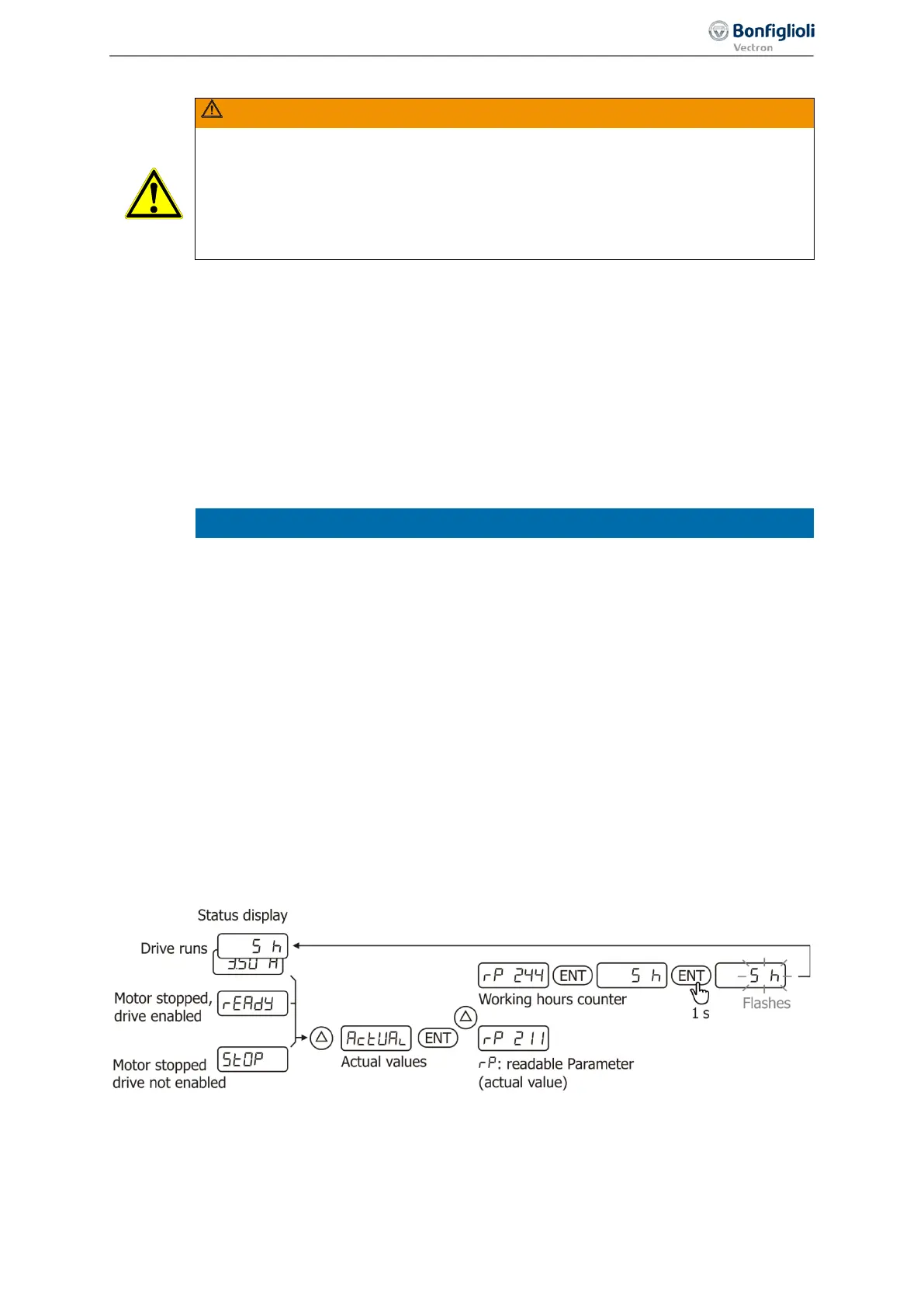
The actual value for permanent display during operation can be selected:
• Select menu “Actual”. Confirm by pressing ENT.
• By means of the arrow keys select the number of the parameter the value of which is to be dis-
played. Confirm by pressing ENT. The value is displayed.
• Press ENT for at least 1 second. The display flashes.
The selected value is displayed permanently during drive operation.
Example: Select the working hours (operating hours in which the output stage of the inverter is ac-
tive) for permanent display.
71
First commissioning 06/2013 Operating Instructions
Agile

 Loading...


