Operational and error diagnosis
14 Operational and error diagnosis
Operation of the frequency inverter and the connected load are monitored continuously. Various func-
tions document the operational behavior and facilitate the operational and error diagnosis.
14.1 Status of digital signals
The status display of the digital input and output signals enables checking of the vari-ous control sig-
nals and their assignment to the corresponding software functions, in particular during commissioning.
Parameters
Status digital inputs 350 and Status digital outputs 351 show decimal values which must
be converted to binary values in order to obtain the status information.
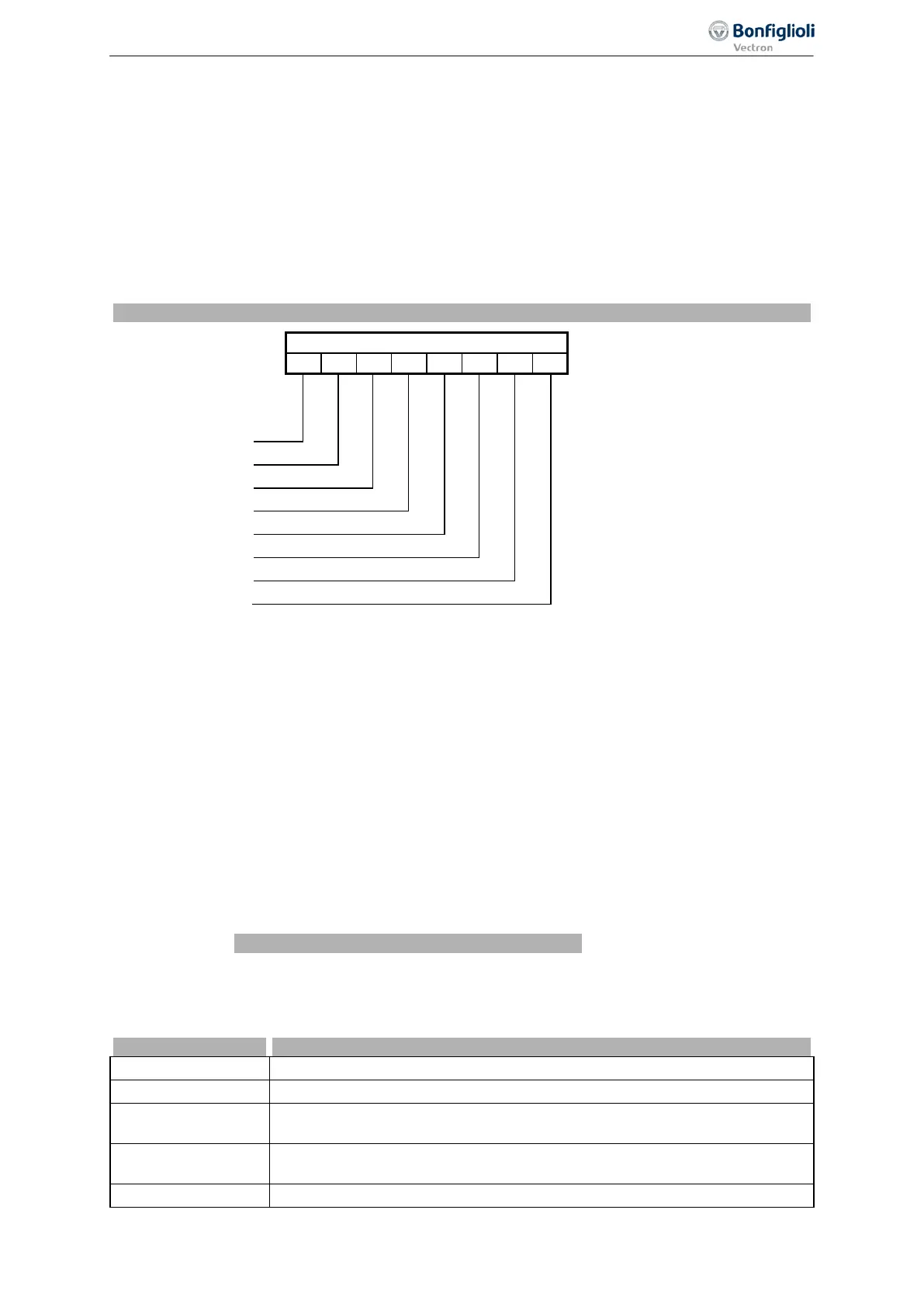
Coding of the status of the digital signals
A decimal value is displayed, indicating the status of the digital signals in bits after conversion into a
binary figure.
Example:
Decimal figure 33 is displayed. Converted into the binary system, the number reads 00100001. Thus,
the following contact inputs or outputs are active:
Digital input or output 1
Digital input or output 6
14.2 Controller status
The controller status can be used to establish which of the control functions are active. If a several
controllers are active at the time, a controller code com-posed of the sum total of the individual codes
is displayed. Display of the controller status via the operator panel can be parameterized via parame-
ter
Controller status message 409.
Coding of the controller status
Voltage controller is in the rise phase according to Operation Mode 670.
C 00 02 UDstop
The output frequency in the case of a power failure is below the Shutdown
Threshold 675.
C 00 04 UDctr
Failure of the mains voltage and power regulation active according to Opera-
tion Mode 670 of the voltage controller.
The DC link voltage has exceeded the Reference DC-Link Limitation 680.
335
Status of digital signals 06/2013 Operating Instructions
Agile

 Loading...


