Parameter descriptions
Backlash
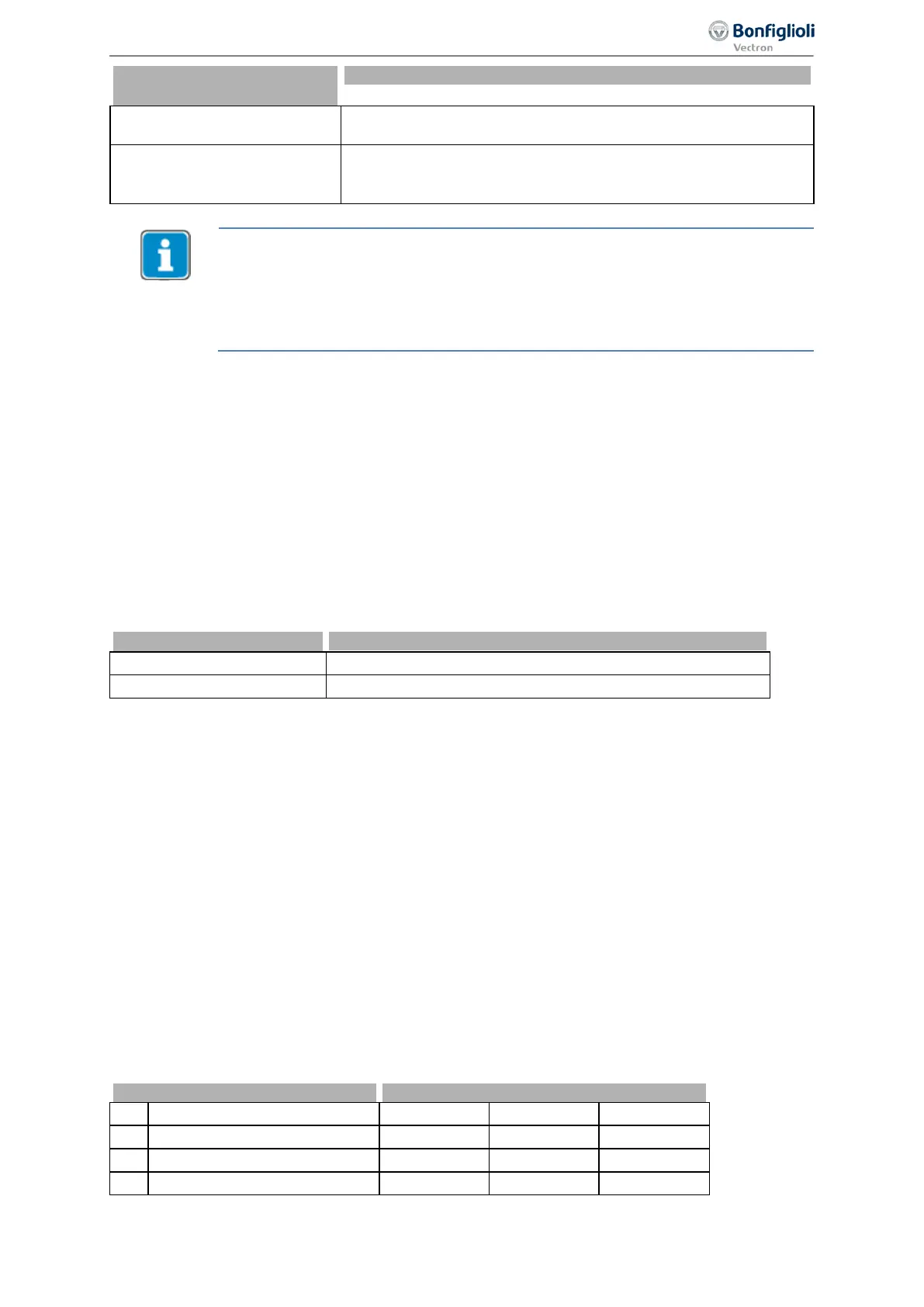
Motor Power off 440
0 -
Off
The switch off of the power stage is not influenced.
Factory setting.
1 -
Active, Fixed Frequency 1
If the control deviation < Backlash 618 and at the same time the
Actual Frequency < Switch-Off Threshold Stop Function 637 the
power stage is switched off.
The Switch off behavior, which is set up by the Stopping behavior (Operation
mode
630) is not changed by Backlash Motor Power off 616
. While this function is
switched on, the power stage is additionally switched off if the control deviation <
Backlash
618 and Actual Frequency < Switch-Off Threshold Stop Function 637
. The
motor is switched on again as soon as the control deviation is larger again than the
set up threshold of
Backlash 618.
7.9.4 Functions of sensorless control
The configurations of the sensorless control contain the following additional functions, which supple-
ment the behavior according to the parameterized V/f characteristic (
Configuration 30 = 110).
7.9.4.1 Slip compensation
660 Operation Mode (slip compensation)
T
he load-dependent difference between the reference speed and the actual speed of the 3-phase
motor is referred to as the slip. This dependency can be compensated by the current meas
-ur
ement in
the output phases of the frequency inverter.
T
he activation of
Operation Mode 660 for the slip compensation enables as speed control without
feedback. The stator frequency and speed are corrected depending on the load.
0 -
Off The slip compensation is deactivated. Factory setting.
1 -
On The load-dependent slip speed is compensated
The slip compensation is activated during the guided commissioning. The Stator Resistance 377 is
required to ensure a correct function and is measured during the guided commissioning.
If no guided commissioning is executed, the slip compensation can be activated manually. In these
cases, enter the value for the
Stator Resistance 377 manually according to the motor data sheet.
For parameter
Configuration 30, setting "110 - IM: sensorless control" (V/f characteristic) must be
selected.
661 Amplification
662 Max. Slip Ramp
663 Frequency Lower Limit
The control behavior of the slip compensation can only be optimized via the parameters in the case of
specific applications. The parameter
Amplification 661 determines the correction of the speed and
the effect of the slip compensation proportionally to the change of load. Parameter
Max. Slip Ramp
662 defines the maximum frequency change per second in order to avoid an overload in the case of a
load change.
The parameter
Frequency Lower Limit 663 determines the frequency as from which the slip compen-
sation becomes active.
661 Amplification 0% 300.0% 100.0%
662 Max. Slip Ramp 0.01 Hz/s 650.00 Hz/s 5.00 Hz/s
663 Frequency Lower Limit 0.01 Hz 999.99 Hz 0.01 Hz
227
Control functions 06/2013 Operating Instructions
Agile

 Loading...


