Error protocol
Output signals in the case of error messages
Errors are signaled via digital signals.
Error Signal
A monitoring function signals an error with indication via parameter Actual
error
259.
1)
For linking to frequency inverter functions.
2)
For output via a digital output. Select the signal source for one of the parameters 531, 532, 533,
554. See chapter 7.6.5 "Digital outputs".
I
n addition to fault messages mentioned, there are further fault messages. However these messages
are only used for internal purposes and are not listed here. If you receive fault mes
-s
ages which are
not listed here, please contact the BONFILGLIOLI customer service.
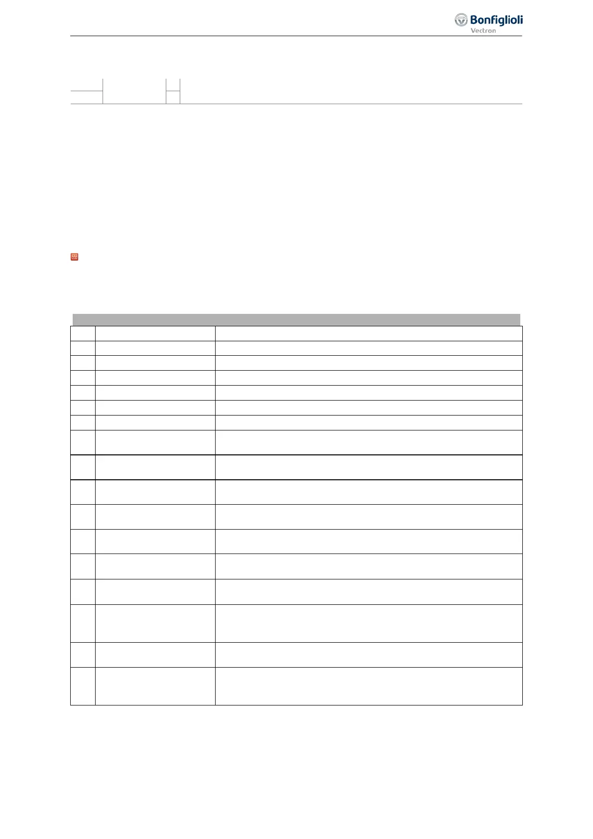
13.2 Error environment
Actual values at the event of a failure
The parameters of the error environment help troubleshooting both in the settings of the frequency
inverter and also in the complete application. The error environment documents the operational be-
havior of the frequency inverter at the time of the last four faults.
No. Description Function
330 DC–link voltage Direct voltage in DC-link.
331 Output voltage Calculated output voltage (motor voltage) of the frequency inverter.
The output voltage (motor voltage) of the frequency inverter.
Measured current in motor phase U.
Measured current in motor phase V.
Measured current in motor phase W.
338 rms Current
Calculated effective output current (motor current) of the frequency
inverter.
339 Isd/reactive current
Current component forming the magnetic flux or the calculated
reactive current.
340 Isq/active current
Current component forming the torque or the calculated active
current.
341
Rotor magnetizing cur-
rent
Magnetizing current relative to the rated motor parameters and the
operating point.
342 Torque
Torque calculated from the voltage, the current and the control
variables.
343 Analog input MFI1A
Input signal at multifunction input 1 (terminal X12.3) in analog
Operation mode MFI1 452 (voltage or current).
344 Analog input MFI2A
Input signal at multifunction input 2 (terminal X12.4) in analog
Operation mode MFI2 562 (voltage or current).
346 Analog output MFO1A
Output signal at multifunction output 1 (terminal X13.6) in setting
"10 - Analog (PWM) MFO1A" of parameter Operation mode MFO1
348
DC-link Cap. Tempera-
ture
Measured capacitor temperature.
349
Repetition frequency
output
Signal at multifunction output 1 in setting "20 - repetition frequency
(FF) MFO1F" for Operation mode MFO1 (X13.6) 550 and according
to selection for RF/PT: Output Value MFO1F 555.
329
Error environment 06/2013 Operating Instructions
Agile

 Loading...


