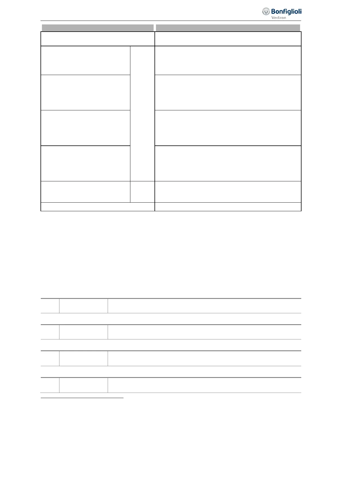
Parameter descriptions
Operation mode 531, 532, 533, 554
51 -
Warning service DC-link
The time remaining until service has expired. See chap-
ter 10.3.1 “DC-link”.
80 -
PLC-Output Buffer 1
1
Output signal of a PLC function. Signal source "2401 -
PLC output buffer 1" is the output signal. The assign-
ment is performed via parameter
PLC-target output 1
1350 or PLC-target output 2 1351.
81 -
PLC-Output Buffer 2
Output signal of a PLC function. Signal source "2402 -
PLC output buffer 2" is the output signal. In a table
function the assignment is performed via parameter
PLC-target output 1 1350 or PLC-target output 2
82 -
PLC-Output Buffer 3
Output signal of a PLC function. Signal source "2403 -
PLC output buffer 3" is the output signal. In a table
function the assignment is performed via parameter
PLC-target output 1 1350 or PLC-target output 2
83 -
PLC-Output Buffer 4
Output signal of a PLC function. Signal source "2404 -
PLC output buffer 4" is the output signal. In a table
function the assignment is performed via parameter
PLC-target output 1 1350 or PLC-target output 2
Obj 0x3003 DigOut 1 to
Obj 0x3003 DigOut 5
2
Sources of CAN objects.
100 to 194 Operation modes inverted (LOW active).
7.6.5.1 Digital message
Signals output via a digital output can be linked to a function of the frequency inverter. The signals
selected for the following parameters can be linked to functions:
−
Operation mode OUT1D (X13.5) 531(digital output)
−
Operation mode OUT2D (X10/relay) 532
−
Operation mode OUT3D (X11.6 )533 (digital input/output)
−
Digital: Source MFO1D 554 (multifunction output)
Signal at digital output OUT1D
175 -
Signal selected via Operation Mode OUT1D (X13.5) 531.
Signal at digital output OUT2D (relay output)
176 -
Digital message
OUT2D relay
Signal selected via Operation Mode OUT2D (X10/relay) 532.
Signal at digital input/output (terminal X11.6)
177 -
Signal selected via Operation Mode OUT3D (X11.6) 533. Set: Operation
Mode Terminal X11.6 558 = „1 - Output OUT3D“.
Signal at multifunction output
181 -
MFO1D
Signal selected via Digital: Source MFO1D 554. Set: Operation Mode
MFO1 (X13.6)
550 = "1 - Digital MFO1D".
1
Refer to application manual "PLC".
2
Comply with instructions on CANopen.
189
Control inputs and outputs 06/2013 Operating Instructions
Agile

 Loading...


