Parameter descriptions
7.10.4 Brake chopper and brake resistor
506 Trigger Threshold
The frequency inverters feature a brake chopper transistor. The external brake resistor is connected
to terminals Rb1 and Rb2. The parameter
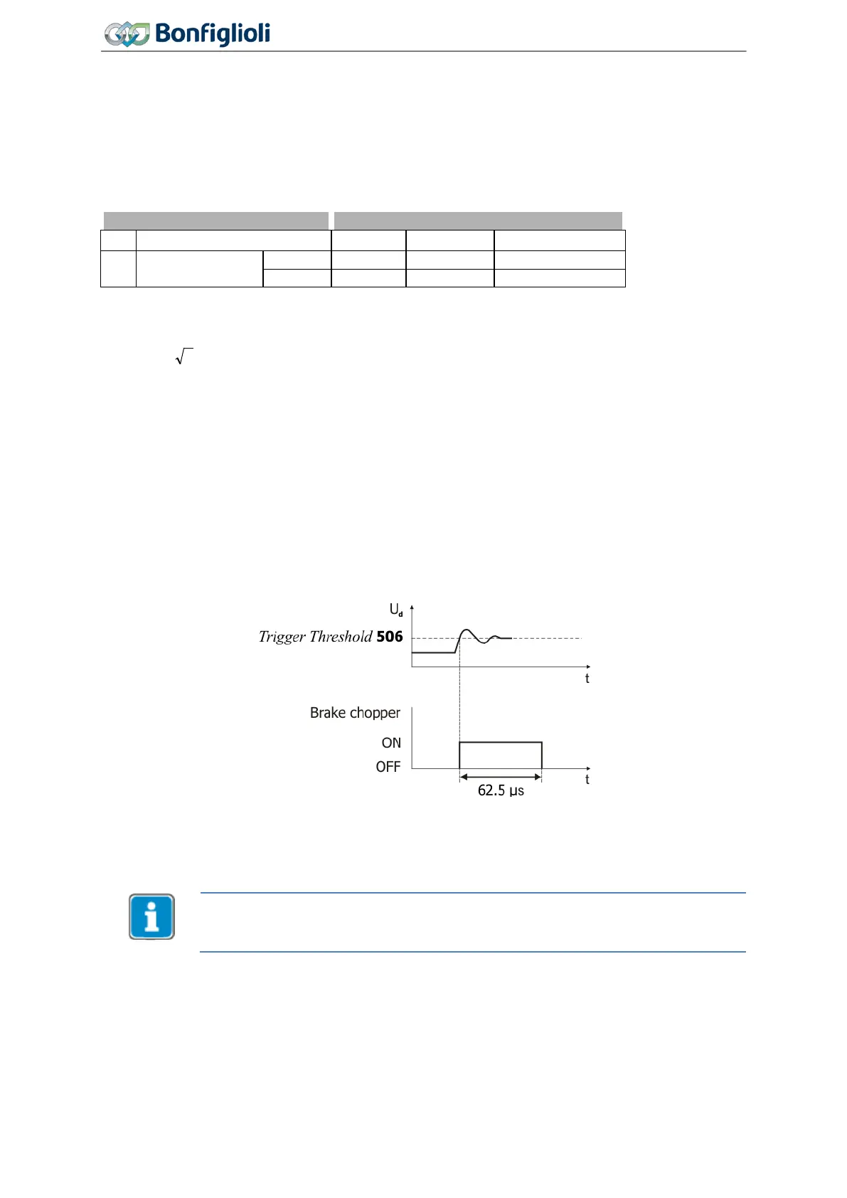
Trigger Threshold 506 defines the switch-on threshold of
the brake chopper. The generator output of the drive, which leads to the increase in the DC link volt-
age, is converted to heat by the external brake resistor above the limit set via parameter
Trigger
Threshold
506.
No. Description Min. Max. Fact. sett.
506 Trigger Threshold
Set parameter
Trigger Threshold 506 such that it is between the maximum DC link voltage which the
mains can generate and the maximum admissible DC link voltage of the frequency inverter.
If the parameter
Trigger Threshold 506 is set larger than the maximum admissible DC link voltage,
the brake chopper cannot become active; the brake chopper is switched off.
If the parameter
Trigger Threshold 506 is set to a value below the DC link voltage generated by the
mains, error message F0705 (chapter 13.1.1 "Error messages") is displayed if the start command is
issued to the frequency inverter.
If the DC link voltage exceeds the maximum value of DC 800 V, error message F0700 (see chapter
13.1.1 "Error messages") will be signaled.
The sampling time of the function is 62.5 µs. The brake chopper remains on for at least 62.5 µs after
the set trigger threshold was exceeded even if the value drops below the trigger threshold within this
period again.
Release or disable brake chopper
Via the signal assigned to parameter
Brake Chopper Release 95, the brake chopper can be released
or disabled. See chapter 7.6.6.13 "Brake chopper release".
Please note that by default the Motor chopper Trigger Threshold 507 and the Trigger
Threshold
506
are set up with different values. Check, that the two thresholds are set
up fittingly for your application.
Please check chapter 7.10.5 “Motor chopper”.
242
Operating Instructions
Agile
06/2013 Special functions

 Loading...


