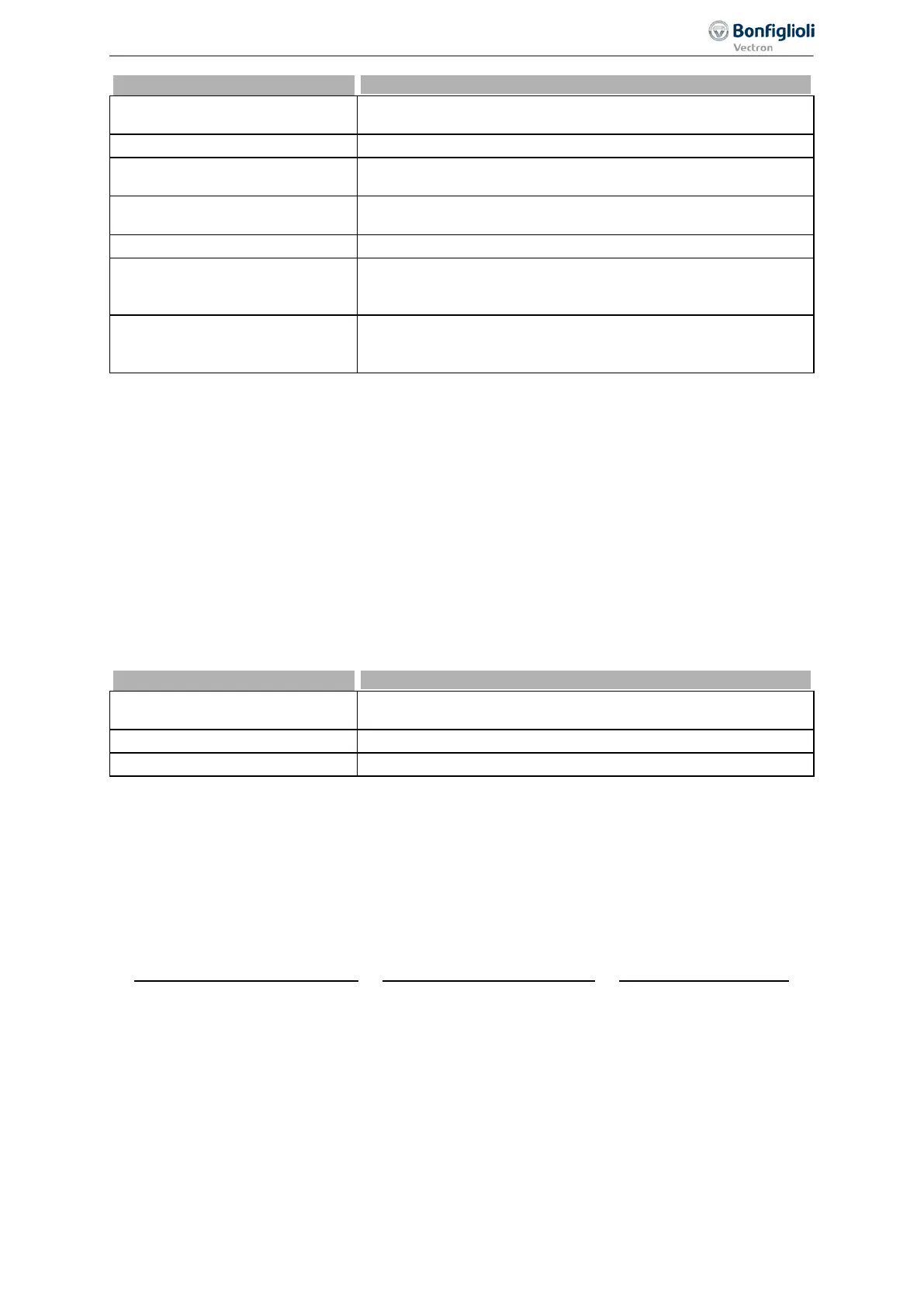
Parameter descriptions
1 -
Voltage 0…10V
Voltage signal (MFI1A), 0 V ... 10 V. Fixed characteristic. Facto-
ry setting.
2 -
Current 0…20 mA Current signal (MFI1A), 0 mA ...20 mA. Fixed characteristic.
3 -
Digital NPN (active: 0 V)
Digital signal (MFI1D) 0 V ... 24 V. Low-switching (with negative
signal).
4 -
Digital PNP (active: 24 V)
Digital signal (MFI1D) 0 V ... 24 V. High-switching (with positive
signal).
5 -
Current 4…20 mA Current signal (MFI1A), 4 mA ...20 mA. Fixed characteristic.
6 -
Voltage, characteristic
Voltage signal (MFI1A), 0 V ... 10 V. The output signal is influ-
enced by the set characteristic. The characteristic can be set via
7 -
Current, characteristic
Current signal (MFI1A) 0 mA … 20 mA. The output signal is in-
fluenced by the set characteristic. The characteristic can be set
via parameters 454 … 457.
Multifunction input MFI1 is configured by default for an analog reference value source with a voltage
signal of 0 V to 10 V.
Alternatively, you can select the operation mode for an analog current signal of 0 … 20 mA or 4 …
20 mA. The current signal is continuously monitored and the fault message "F1407" displayed if the
maximum figure is exceeded.
7.6.1.1 Multifunction input set as analog input MFI1A
The Multifunction input can be evaluated either as analogue or digital signal. In the following the
evaluation for analogue signals is described.
7.6.1.1.1 Voltage input and current input
For parameter
Operation Mode MFI1 452, "1 - Voltage 0…10V", "2 - Current 0…20 mA" or "5 - Cur-
rent 4…20 mA" must be selected.
1 -
Voltage 0…10 V
Voltage signal (MFI1A), 0 V ... 10 V. Fixed characteristic.
Factory setting.
2 -
Current 0…20 mA Current signal (MFI1A), 0 mA ...20 mA. Fixed characteristic.
4 -
Current 4…20 mA Current signal (MFI1A), 4 mA ...20 mA. Fixed characteristic.
The analog input signal is mapped to a reference frequency or percentage.
Voltage 0…10 V
Parameter
Operation Mode MFI1 452 is set to "1 - Voltage 0…10 V". The coordinates of the points
relate, as a percentage, to the analog signal with 9.8 V and parameter
Maximum Frequency 419 or
parameter
Maximum Reference Percentage 519. The zero-crossing of the frequency or the percent-
age value lies at 0.2 V. The deviations from 10 V and 0 V allow the operation even with voltage sup-
plies that have small deviations from the nominal values.
Incliniation:
9.8 0.2
=
9.6
419
=
9.6
. 519
Current 0…20 mA
Current 0…20 mA
Parameter
Operation Mode MFI1 452 must be set to "2 - Current 0…20 mA". The coordinates of the
points relate, as a percentage, to the analog signal with 19.6 mA and parameter
Maximum Frequen-
cy
419 or parameter Maximum Reference Percentage 519. The zero-crossing of the frequency or the
percentage value lies at 0.4 mA. The deviations from 20 mA and 0 mA allow the operation even with
voltage supplies that have small deviations from the nominal values.
169
Control inputs and outputs 06/2013 Operating Instructions
Agile

 Loading...


