Parameter descriptions
Incliniation:
19.6 0.4
=
19.2
419
=
19.2
. 519
Current 4…20 mA
Parameter
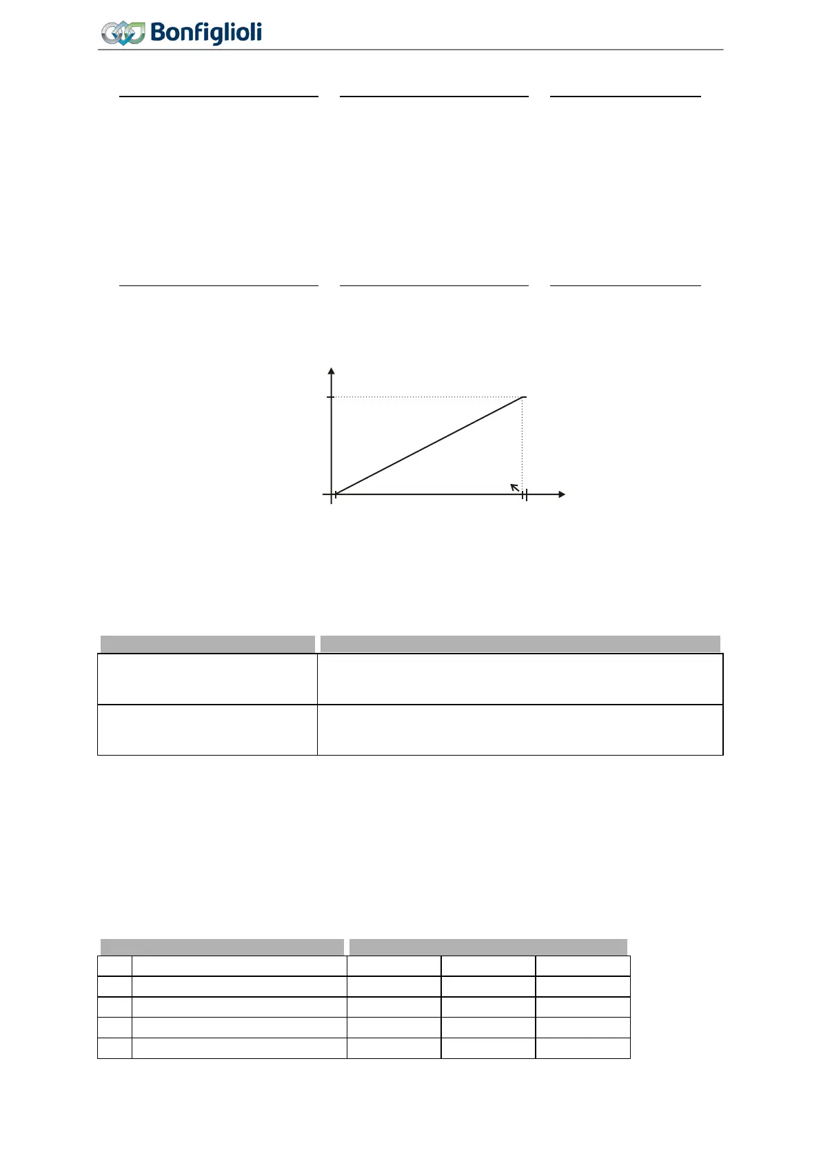
Operation Mode MFI1 452 must be set to "5 - Current 4…20 mA". The coordinates of the
points relate, as a percentage, to the analog signal with 19.6 mA and parameter
Maximum Frequency
419 or parameter Maximum Reference Percentage 519. The zero-crossing of the frequency or the
percentage value lies at 4.4 mA. The deviations from 20 mA and 4 mA allow the operation even with
voltage supplies that have small deviations from the nominal values.
Incliniation:
19.6 4.4
=
15.2
419
=
15.2
. 519
7.6.1.1.2 Voltage input characteristic and current input characteristic
For parameter
Operation Mode MFI1 452, "6 - Voltage, characteristic" or "7 - Current, characteristic"
must be selected.
6 -
Voltage, characteristic
Voltage signal (MFI1A), 0 V ... 10 V. The output signal is influ-
enced by the set characteristic. The characteristic can be set via
7 -
Current, characteristic
Current signal (MFI1A) 0 mA … 20 mA. The output signal is in-
fluenced by the set characteristic. The characteristic can be set
via parameters 454 … 457.
454 Characteristic Curve Point X1
455 Characteristic Curve Point Y1
456 Characteristic Curve Point X2
457 Characteristic Curve Point Y2
The analog input signal is mapped to a reference frequency or percentage. Parameterization can be
done via two points of the linear characteristic of the reference value channel.
Point 1 with coordinates X1 and Y1 and point 2 with coordinates X2 and Y2 can be set in four data
sets.
454 Characteristic Curve Point X1 0.00% 100.00% 2.00%
455 Characteristic Curve Point Y1 -100.00% 100.00% 0.00%
456 Characteristic Curve Point X2 0.00% 100.00% 98.00%
Characteristic Curve Point Y2
0 V
(0 mA)
(4 mA)
50 Hz
+10 V
(+20 mA)
(+20 mA)
9.8 V
0.2 V
f [Hz]
U [V]
P452=1
(P452=2)
(P452=5)
170
Operating Instructions
Agile
06/2013 Control inputs and outputs

 Loading...


