Parameter descriptions
The coordinates of the points relate, as a percentage, to the analog signal with 10 V or 20 mA and
parameter
Maximum Frequency 419 or parameter Maximum Reference Percentage 519. The direc-
tion of rotation can be changed via the digital inputs and/or by selection of the points.
WARNING
The monitoring of the analog input signal via the parameter
453 demands the check of parameter Characteristic Curve Point X1 454.
In the settings
− "6 - Voltage, characteristic" or
− "7 - Current, characteristic"
of parameter
Operation Mode MFI1 452, the following characteristic is effective:
Point 1:
Hz 0.00Hz 50.000.00%Y1 =⋅=
Point 2:
Hz 0.005Hz 50.000.00%10Y2 =⋅=
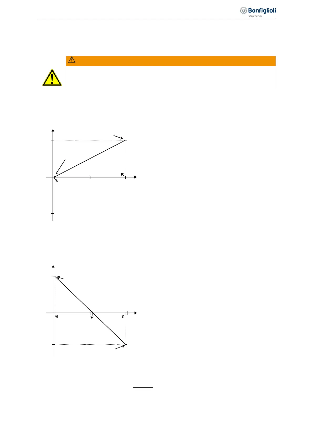
The characteristic can be adjusted via parameters 454 … 457 of the application.
The freely configurable characteristic enables setting a tolerance at the ends as well as a reversal of
the direction of rotation.
The following example shows the inverse reference value specification with additional reversal of the
direction of rotation. This is often used in pressure control systems.
Point 1:
Hz 50.00Hz 50.000.00%10Y1 =⋅=
Point 2:
Hz 0.004Hz 50.000.00%8Y2 −=⋅−=
The change of direction of rotation is done in this exam-
ple at an analog input signal of 5.5 V. pos./neg. maxi-
mum figure.
The definition of the analog input characteristic can be calculated via the two-point form of the line
equation. The speed Y of the drive is controlled according to the analog control signal X.
( )
Y1X1X
X1-X2
Y1-Y2
Y +−⋅=
Pos. maximum value
Neg. maximum value
(X1=2%/Y1=0%)
0 V
(0 mA)
50 Hz
+10 V
(+20 mA)
9.8 V
0.2 V
(X2=98%/Y2=100%)
Y
X
Pos. maximum value
(X1=2%/Y1=100%)
0 V
(0 mA)
5.5 V
9.8 V0.2 V
+10 V
(+20 mA)
(X2=98%/Y2=-80%)
Y
X
-40 Hz
50 Hz
171
Control inputs and outputs 06/2013 Operating Instructions
Agile

 Loading...


