Parameter descriptions
Scaling
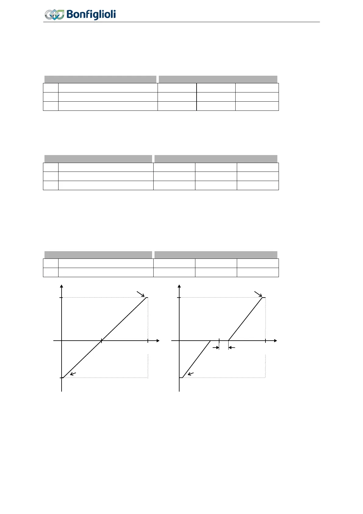
The analog input signal is mapped to the freely configurable characteristic. The maximum admissible
setting range of the drive can be set via the frequency limits or percentage limits. In the case of the
parameterization of a bipolar characteristic, the set minimum and maximum limits for both directions
of rotation are effective. The percentage values of the characteristic points are relative to the limits
selected.
No. Description Min. Max. Fact. sett.
418 Minimum Frequency 0.00 Hz 999.99 Hz 3.50 Hz
419 Maximum Frequency 0.00 Hz 999.99 Hz 50.00 Hz
The control system uses the maximum value of the output frequency, which is calculated from the
Maximum Frequency 419 and the compensated slip of the drive mechanism. The frequency limits
define the speed range of the drive, and the percentage values supplement the scaling of the analog
input characteristic in accordance with the functions configured.
No. Description Min. Max. Fact. sett.
Minimum Reference Percentage
519 Maximum Reference Percentage 0.00% 300.00% 100.00%
450 Tolerance Band
The analog input characteristic with change of sign of the reference value can be adapted by the pa-
rameter
Tolerance Band 450 of the application. The adjustable tolerance band extends the zero pas-
sage of the speed relative to the analog control signal. The parameter value (percent) is relative to
the maximum current or voltage signal.
Hysteresis
The default
Minimum Frequency 418 or Minimum Reference Percentage 518 extends the parameter-
ized tolerance band to the hysteresis.
Pos. maximum value
Neg. maximum value
0 V
(0 mA)
+10 V
(+20 mA)
(X1/Y1)
(X2/Y2)
Pos. maximum value
zero point
tolerance band
Neg. maximum value
0 V
(0 mA)
+10 V
(+20 mA)
(X1/Y1)
(X2/Y2)
172
Operating Instructions
Agile
06/2013 Control inputs and outputs

 Loading...


