EasyManua.ls Logo

BONFIGLIOLI Agile User Manual

BONFIGLIOLI Agile
360 pages
To Next Page IconTo Next Page
To Previous Page IconTo Previous Page
Page #26 background image
Device overview
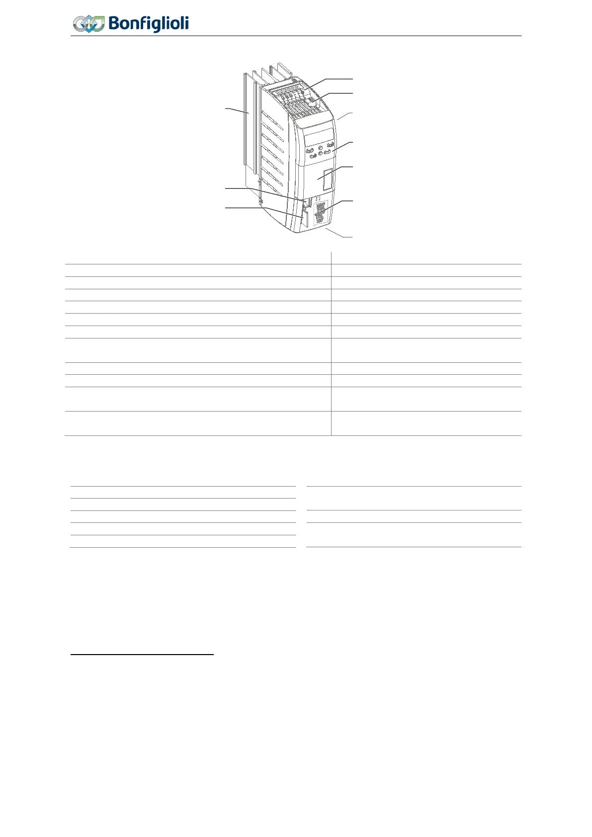
3.4 Overview of components and connection terminals
See
Mains voltage connection
Chapter 5.5
The safety instructions must be complied with strictly.
Chapter 5.1
Motor Connection
Chapter 5.6
The safety instructions must be complied with strictly.
Chapter 5.1
Control terminals and relay output
Chapter 5.7
The safety instructions must be complied with strictly.
Chapter 5.1
CAN connection terminals
Separate instructions on System bus or
CANopen®
1
.
Operator panel
Chapter 6.1
Port for memory card (MMC)
Chapter 7.10.11 and 12.8
Communication interface X21
2
Separate instructions on VABus or Mod-
bus.
Port for one of the optional communication modules (see
previous chapter for list)
Separate instructions on the protocols.
3.5 Number of control terminals
4 digital inputs
2 digital inputs for enable
1 digital input/output
2 multifunction inputs: digital/analog input
1 digital output
1 multifunction output: digital/analog/frequency
1 input for external voltage supply DC 24 V
1 reference voltage output DC 10 V
1 voltage output DC 24 V
1 relay output, potential-free
Control terminals for system bus or protocol
CANopen®
1
The products for CANopen® communication comply with the specifications of the user organization CiA® (CAN
in Automation).
2
Install an interface adapter for connection of a PC. This enables configuration and monitoring using the PC
software VPlus.
Operator panel
Plug-in section for
optional communication module
Memory card slot
Heat sink
Communication interface X21
with RJ45 connection
Motor connection
Mains connection
Relay output, potential-free
Control terminals
Type plate
26
Operating Instructions
Agile
06/2013 Overview of components and connection
terminals

Table of Contents

Other manuals for BONFIGLIOLI Agile

Question and Answer IconNeed help?

Do you have a question about the BONFIGLIOLI Agile and is the answer not in the manual?

BONFIGLIOLI Agile Specifications

General IconGeneral
Fieldbus CommunicationCANopen, Modbus RTU
Cooling MethodNatural convection
Relative Humidity5% to 95% (non-condensing)
Enclosure RatingIP20
ProtectionOvervoltage, Overtemperature

Summary

General Information about the Documentation

Documentation Overview

Details available manuals like Quick Start Guide, Operating Instructions, and Application Manual for system setup.

Warranty and Liability Information

Outlines the manufacturer's warranty terms and limitations of liability for product use.

Obligation, Copyright, and Storage

Covers user obligations, copyright information, and proper storage of the documentation.

General Safety Instructions and Information on Use

Terminology and Safety Roles

Defines key roles such as Operator, Qualified Staff, and Expert for safe operation.

Designated Use and Misuse

Specifies the intended application and potential hazards associated with misuse.

Residual Risks and Safety Signs

Identifies typical residual hazards and emphasizes compliance with safety signs.

Warning Information and Symbols

Explains hazard classes, symbols, and prohibition signs used in the manual for safety.

Operator Responsibilities and Guidelines

Outlines operator responsibilities, plant documentation, and general work safety.

Organizational Measures

Covers training, third-party product use, transport, storage, and electrical connections.

Device Overview

Inverter Type and Warning Signs

Details how to identify the inverter model and interpret warning labels on the device.

Type Designation and Components

Explains the device's type designation system and provides an overview of its components.

Software Version Identification

Describes the location and method for identifying the inverter's software version.

Mechanical Installation

Installation Safety and Guidelines

Covers essential safety precautions, mounting distances, and installation restrictions for the inverter.

Installation Sizes and Dimensions

Provides specific dimensions and mounting details for different inverter sizes (Size 1, 2, 3).

Electrical Installation

Electrical Installation Safety and Best Practices

Emphasizes safety measures, grounding, and connection conditions for electrical installation.

EMC Information and Cable Shielding

Details measures for Electromagnetic Compatibility (EMC), including cable shielding and bonding.

Mains and Motor Connection Procedures

Explains the correct procedures for connecting the mains supply and the motor to the inverter.

Commissioning

Operator Panel Functions and Menu Navigation

Describes the operator panel's buttons, menus, and navigation for parameter settings.

First Commissioning Procedures

Guides users through the initial setup for asynchronous and synchronous motors.

Parameter Descriptions

Inverter Data and Machine Data

Details parameters related to serial number, software version, and motor specifications.

Operational Behavior Settings

Covers parameters for controlling start, stop, direction, speed, and operational modes.

Error and Warning Handling

Explains how the inverter manages errors and warnings, including message codes and diagnosis.

Reference Values and Ramps

Defines how reference values like frequency and percentage are set, scaled, and ramped.

Control Inputs and Outputs Configuration

Details the configuration and functions of digital and analog inputs/outputs and their signals.

Energy Saving

Energy Saving Function Configuration

Explains how to set up the energy saving function for optimized motor power consumption.

Standby Mode Options

Describes settings for reducing power consumption when the inverter is idle or in standby.

Actual Values

Actual Values of Frequency Inverter

Lists real-time values from the frequency inverter, like DC-link voltage, modulation, and frequency.

Actual Values of Machine

Provides actual values related to the connected motor, such as stator frequency, current, and torque.

Service

Regular Service Work and Cleaning Procedures

Outlines recommended maintenance tasks and cleaning instructions for the frequency inverter.

Service Interval Monitoring

Explains how to monitor and reset service intervals for components like DC-link and fans.

Technical Data

General Technical Data and Compliance

Covers CE conformity, EMC directives, UL approval, and general environmental conditions.

Device Data by Model and Power

Lists specific technical data, dimensions, and ratings for different Agile series models and power ratings.

OPTIONS

Safety Precautions for Options

Highlights safety considerations when installing and using optional components.

Shield Sheets for EMC Compliance

Details the installation of optional shield sheets for control and motor cables to ensure EMC conformity.

Input Filters and Line Chokes

Explains the types of input filters and line chokes for EMC suppression and their installation requirements.

Assembly Variants and Mounting Options

Describes different assembly options like feed-through, cold plate, vibration-proof, and DIN rail mounting.

ERROR PROTOCOL

Error List and Messages

Provides a comprehensive list of error codes, their meanings, and initial troubleshooting steps.

Error Environment and Troubleshooting

Details actual values recorded at the time of a fault for diagnostic purposes and troubleshooting guidance.

OPERATIONAL AND ERROR DIAGNOSIS

Status of Digital Signals and Controller Status

Explains how to interpret the status of digital signals and controller codes for operational diagnosis.

Warning Status and Application Warnings

Describes how to interpret warning status codes and application-specific warnings for proactive issue identification.

PARAMETER LIST

Actual Values (Menu Actual)

Lists all actual values that can be read from the frequency inverter for monitoring and diagnostics.

Parameters (Menu PARA)

Provides a comprehensive list of all settable parameters, their units, ranges, and chapter references.

Related product manuals