Parameter descriptions
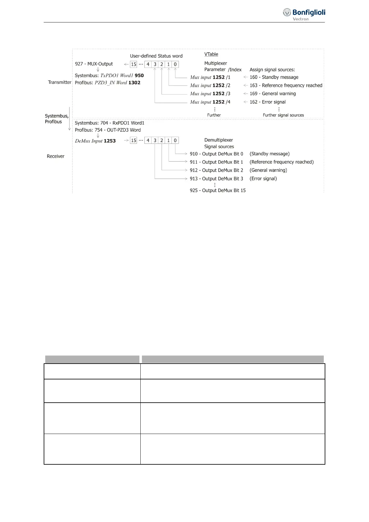
Example: Transfer of a user-defined status word from a slave to a master via system bus or Profibus,
parameterization of multiplexer and demultiplexer using PC application VTable in VPlus
Settings on transmitter:
• In VPlus, start application VTable via the button bar.
• In VTable assign the required signal sources for sending to parameter
Mux. Inputs 1252 index 1
to index 16. A setting for index 0 results in this setting being taken over for all other indices.
• Assign signal source “927 – Output MUX” to a TxPDO process data parameter of the system bus
or a PZDx-IN process data parameter of Profibus.
Settings on receiver:
• Assign the corresponding RxPDO signal sources of the system bus or OUT-PZD signal sources of
Profibus to parameter
DeMux Input 1253.
The transmitted signals are available at the receiver as signal sources 910 to 925.
7.6.7 Input PWM/repetition frequency/pulse train
496 Operation Mode IN2D (PWM/repetition frequency/pulse train)
A PWM signal (pulse-width modulated signal), frequency signal or a pulse train (pulse sequence) sig-
nal can be used for definition of a reference value. The signal at digital input IN2D (at terminal X11.5)
is evaluated according to the selected
Operation Mode IN2D 496.
0 -
Off
The PWM signal or repetition frequency is zero.
Factory setting.
10 -
PWM, 0% – 100%
PWM signal detection at digital input IN2D (at terminal X11.5).
0 … 100% of Maximum Reference Percentage 519 or 0 … 100%
of
419. See
7.6.7.1 “PWM input”.
11 -
PWM, -100% – 100%
PWM signal detection at digital input IN2D (at terminal X11.5).
-100 … 100% of Maximum Reference Percentage 519 or
-100 … 100% of
Maximum Frequency 419. See 7.6.7.1 “PWM
20 -
RF Single Evaluation
Repetition frequency input at digital input IN2D (at terminal
X11.5). One edge of the frequency signal is evaluated. The signal
can also be evaluated as a percentage. See
7.6.7.2 “Repetition
207
Control inputs and outputs 06/2013 Operating Instructions
Agile

 Loading...


