Parameter descriptions
453 Error/Warning Behaviour
For monitoring the analog input signal, an operation mode can be selected via parameter
Er-
ror/Warning Behaviour
453.
Error/Warning Behaviour 453
0 - Off The input signal is not monitored. Factory setting.
1 - Warning < 1V/2 mA
If the input signal is lower than 1 V or 2 mA, a warning message
is issued.
2 - Shutdown < 1V/2 mA
If the input signal is lower than 1 V or 2 mA, a warning and fault
message is issued. The drive is decelerated according to stop-
3 -
Error-Switch-Off
< 1V/2 mA
If the input signal is lower than 1 V or 2 mA, a warning and fault
message is issued and the drive coasts to a standstill (stopping
Monitoring of the analog input signal is active regardless of the enable of the frequency inverter.
Operation mode 2 defines the shut-down and stopping of the drive, regardless of the setting of pa-
rameter
Operation Mode 630 for the stopping behavior. The drive is stopped according to stopping
behavior 2. If the set holding time has expired, an error message is issued. The drive can be started
again by switching the start signal on and off.
Operation mode 3 defines the free coasting of the drive (as described in stopping behavior 0), regard-
less of the setting of parameter
Operation Mode 630 for the stopping behavior.
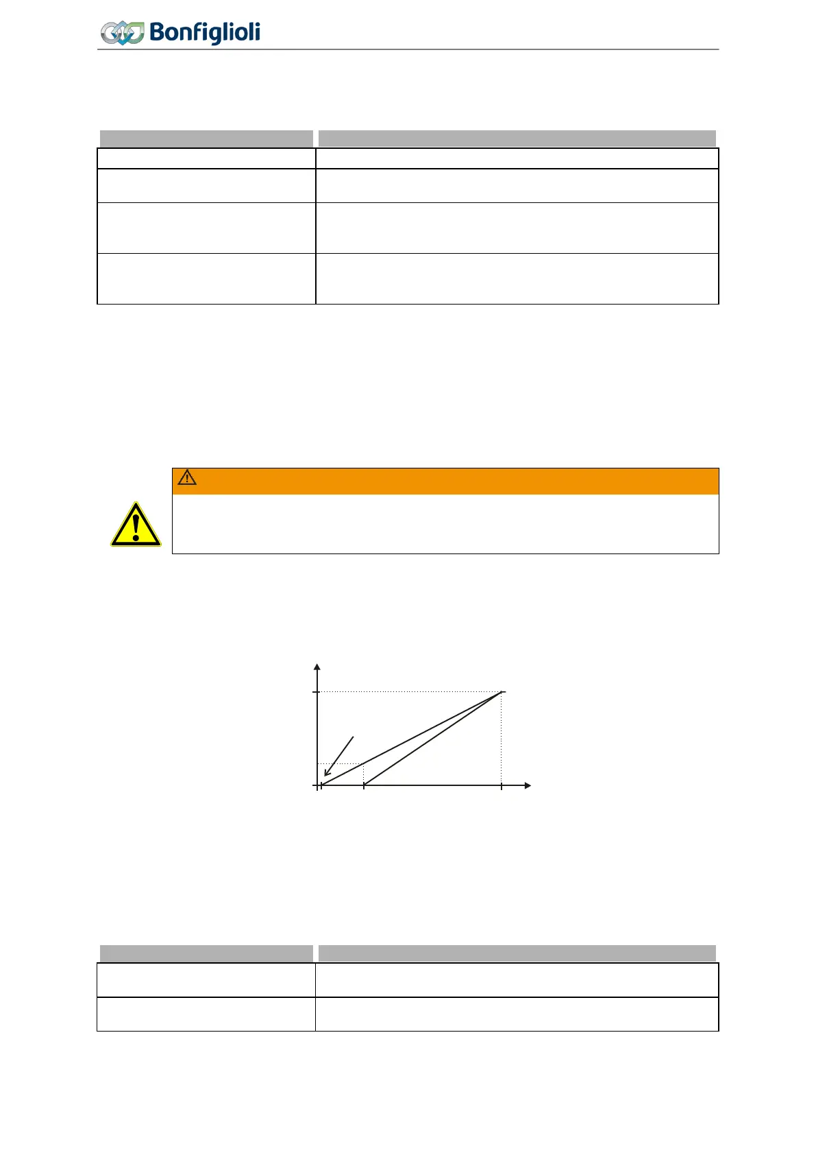
WARNING
The monitoring of the analog input signal via the parameter
453 demands the check of parameter Characteristic Curve Point X1 454.
Example: Error/Warning Behaviour 453 = "2 - Shutdown < 1V/2mA" or "3 - Error Switch-Off <
1V/2mA". In the factory settings of the parameter
Characteristic Curve Point X1 454 shutting down
or error switch-off are affected at an output frequency ≠ 0 Hz. If shutting down or error switch-off are
to be effected at an output frequency of 0 Hz, the Point X1 must be adjusted (e.g. X1=10% /1 V).
7.6.1.2 Multifunction input set as digital input MFI1D
Multifunction input MFI1 (terminal X12.3) can be configured as a digital input. Via parameter Opera-
tion Mode MFI1
452, the evaluation can be selected as PNP (high-switching) or NPN (low-switching).
The multifunction input set as digital input can be linked to the functions of the frequency inverter.
Signal "76 - MFI1D" must be assigned a function.
3 -
Digital NPN (active: 0 V)
Digital signal (MFI1D) 0 V ... 24 V. Low-switching (with negative
signal).
4 -
Digital PNP (active: 24 V)
Digital signal (MFI1D) 0 V ... 24 V. High-switching (with positive
signal).
50 Hz
9.8 V0.2 V
Y
X
0 Hz
(X1=2%/Y1=0%)
1 V
174
Operating Instructions
Agile
06/2013 Control inputs and outputs

 Loading...


