Parameter descriptions
66 Fixed Frequency Change-Over 1
67 Fixed Frequency Change-Over 2
131 Fixed Frequency Change-Over 3
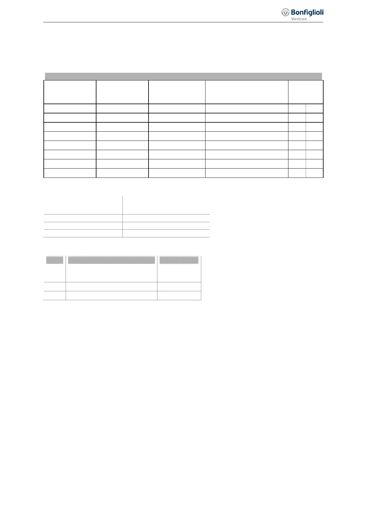
By combining the logic states of the fixed frequency change-over inputs 1, 2 and 3, fixed frequencies
1 through 8 (parameters 480 to 488) can be selected.
Selection of fixed frequencies
Change-Over 1
Change-Over 2
Change-Over 3
Active fixed value
setting
0 0 0
480
1 0 0
481
1 1 0
482
0 1 0
483
0 1 1
485
486
1 0 1
0 0 1
0 = contact open 1 = contact closed
Number of fixed frequencies
per data set
Fixed frequency change-over factory settings:
No. Parameters Setting
66 Fixed frequency change-over 1 74 – IN4D
Fixed frequency change-over 2
Fixed frequency change-over 3
If the data set changeover function is used additionally via parameters
Data Set Change-Over 1 70
and
Data Set Change-Over 2 71, you can preset up to 32 fixed frequencies as reference values.
The fixed frequency changeover can also be controlled via digital signals (instead of digital inputs) by
functions of the frequency inverter.
Via parameter
Operation Mode 493, you can change the direction of rotation of the motor. See chap-
ter 7.5.1.2 "Positive and negative reference frequencies". The direction of rotation can also be preset
with the digital signal sources assigned to the parameters
Start Clockwise 68 and Start Anticlock-
wise
69.
Via the reference frequency channel (see chapter 7.5.1 "Reference frequency channel"), the fixed
reference values can be selected and linked to other reference value sources.
7.5.1.4 Ramps
420 Acceleration (Clockwise)
421 Deceleration (Clockwise)
422 Acceleration Anticlockwise
423 Deceleration Anticlockwise
The ramps determine how quickly the frequency value is changed if the reference value changes or
after a start, stop or brake command. The maximum admissible ramp gradient can be selected ac-
cording to the application and the current consumption of the motor.
147
Reference Values 06/2013 Operating Instructions
Agile

 Loading...


