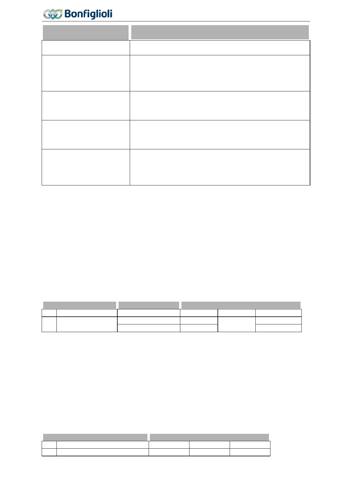
Parameter descriptions
Operation mode real-time
tuning 1520
0 - Off
Real-time tuning is switched off. The controller settings and motor
parameters are not changed during operation. Factory setting.
1 - On
Real-time tuning is switched on. After shut-down or restart of the
frequency inverter or after a data set changeover, the changed
controller parameters are deleted again and replaced by the static
values. The static values contain the motor data measured during
3 - Latching
Real-time tuning is switched on. Optimized control parameters are
saved after shut-down of the frequency inverter (non-volatile).
Each data set is saved separately. In this way, real-time tuning
may also be used for operating cases with motor changeover.
5 - Taking Over
Real-time tuning is switched on. Optimized control parameters are
not saved after shut-down or restart of the frequency inverter.
Optimized controller settings are applied in a new data set after a
7 -
Latching and Taking
Over
Combination of "Latching" and "Taking Over". Real-time tuning is
switched on. Optimized control parameters are saved after shut-
down or restart of the frequency inverter (non-volatile). Optimized
controller settings are applied in a new data set after a data set
7.10 Special functions
The configurable functions of the corresponding control methods enable another field of application of
the frequency inverters. The integration in the application is made easier by special functions.
7.10.1 Pulse width modulation
400 Switching Frequency
The motor noises can be reduced by changing over the parameter
Switching Frequency 400. A re-
duction of the switching frequency should be up to a maximum ration of 1:10 to the frequency of the
output signal for a sine-shaped output signal. The maximum possible switching frequency depends on
the drive output and the ambient conditions. For the required technical data refer to the correspond-
ing table and the device type diagrams.
400 Switching Frequency
16 kHz
The factory setting of parameter Switching Frequency 400 depends on the setting of parameter Con-
figuration
30.
401 Min. Switching Frequency
The heat losses increase proportionally to the load point of the frequency inverter and the switching
frequency. The automatic reduction adjusts the switching frequency to the current operating state of
the frequency inverter in order to provide the output performance required for the drive task at the
greatest possible dynamics and a low noise level.
The switching frequency is adapted between the limits which can be set with the parameters
Switch-
ing Frequency
400 and Min. Switching Frequency 401. If the Min. Switching Frequency 401 is larg-
er than or equal to the
Switching Frequency 400, the automatic reduction is deactivated.
240
Operating Instructions
Agile
06/2013 Special functions

 Loading...


