Parameter descriptions
7.6.6.1 List of control signals
• Select the function that is to be controlled. For example Start drive in anticlockwise operation.
• Select the control signal for the parameter of the function. For example select “74 - IN4D” for
parameter
Start Anticlockwise 69. In this case the drive starts anticlockwise operation if a signal
applies on digital input IN4D (enable signal must also be set).
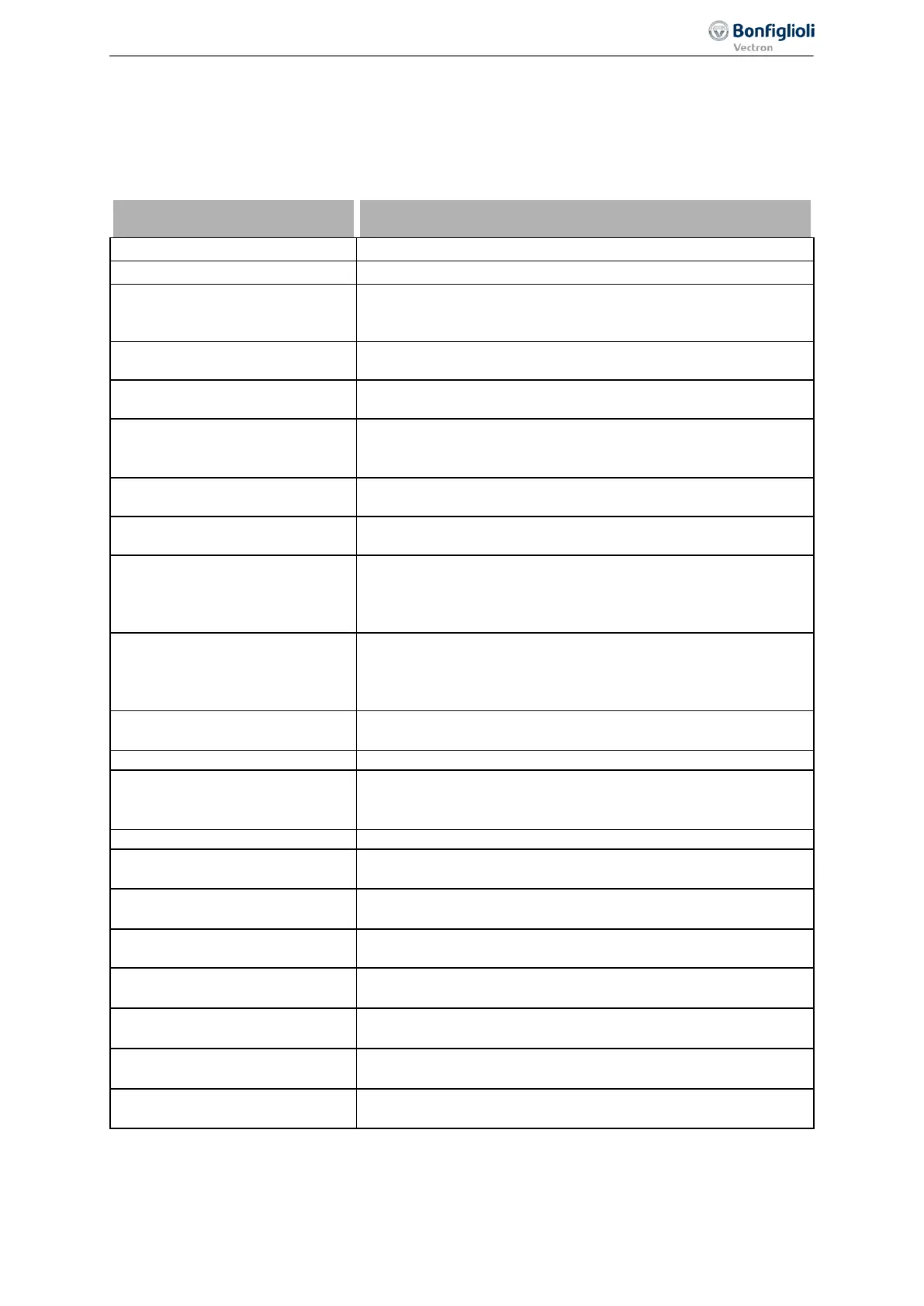
6 -
On Signal input is switched on.
Signal input is switched off.
70 -
Inverter Release
Enable signal of the frequency inverter via digital inputs STOA
(X11.3) and STOB (X13.3). Or enable signal in remote mode via
71 -
IN1D
Signal at digital input IN1D (X11.4). Or signal in remote mode
via communication interface.
72 -
IN2D
Signal at digital input IN2D (X11.5). Or signal in remote mode
via communication interface.
73 -
IN3D
Signal at digital input IN3D (digital input/output, X11.6) in Op-
eration Mode Terminal X11.6 558 = "0 - input IN3D". Or signal
in remote mode via communication interface.
74 -
IN4D
Signal at digital input IN4D (X12.1). Or signal in remote mode
via communication interface.
75 -
IN5D
Signal at digital input IN5D (X12.2). Or signal in remote mode
via communication interface.
76 -
MFI1D
Signal at multifunction input MFI1 (X12.3) in Operation mode
MFI1 452 "3 - digital NPN (active: 0 V)" or "4 - digital PNP (ac-
tive: 24 V)". Or signal in remote mode via communication inter-
77 -
MFI2D
Signal at multifunction input MFI2 (X12.) in Operation Mode
MFI2 562 "3 - Digital NPN (active: 0 V)" or "4 - Digital PNP
(active: 24 V)". Or signal in remote mode via communication
157 -
Warning Mask
The defined warning mask of parameter Create Warning Mask
536 signals a critical operating point.
Frequency inverter is initialized and ready for operation.
161 -
Run Signal
Enable signals (STOA and STOB) and a start command (Start
Clockwise 68 or Start Anticlockwise 69) are applied, output
Monitoring function signals an operational fault.
163 -
Reference Frequency
reached
Signal when the Actual Frequency 241 has reached the refer-
ence frequency
164 -
Setting Frequency
The actual Stator Frequency 210 is higher than the value of
Setting Frequency 510.
165 -
Warning Ixt
The monitoring functions report an overload of the frequency
inverter
166 -
Warning Heat Sink Tem-
perature
Maximum heat sink temperature T
K
minus the Warning Limit
Heat Sink Temp. 407 reached.
167 -
Warning Inside Tempera-
ture
Maximum inside temperature T
i
minus the Warning Limit Inside
Temp. 408 reached.
168 -
Warning Motor Tempera-
ture
Warning behavior according to parameterized Operation Mode
Motor Temp. 570 at maximum motor temperature T
PTC
.
169 -
General Warning
Signal when Warnings 269 are displayed with a critical operat-
ing point
197
Control inputs and outputs 06/2013 Operating Instructions
Agile

 Loading...


