Parameter descriptions
The electronic gear is deactivated. Factory setting.
1 -
P. 685 Numera-
tor/P. 686 Denom-
inator
The repetition frequency value specified via the repetition frequency input
is multiplied by the gear factor. This is the reference frequency for the
slave drive.
The gear factor is calculated from the values of parameters Gear Factor
Numerator 685 and Gear Factor Denominator 686.
2 -
Analog Numera-
tor/P. 686 Denom-
inator
The repetition frequency value specified via the repetition frequency input
is multiplied by the gear factor. This is the reference frequency for the
slave drive.
The numerator of the gear factor is scaled using the Reference Percentage
Source 1
476. The denominator of the gear factor is the value set in pa-
rameter Gear Factor Denominator 686.
3 -
P. 685 Numera-
tor/Analog De-
nominator
The repetition frequency value specified via the repetition frequency input
is multiplied by the gear factor. This is the reference frequency for the
slave drive.
The numerator of the gear factor is the value set in parameter Gear Fac-
tor Numerator
685. The denominator of the gear factor is scaled using the
Reference Percentage Source 1
476.
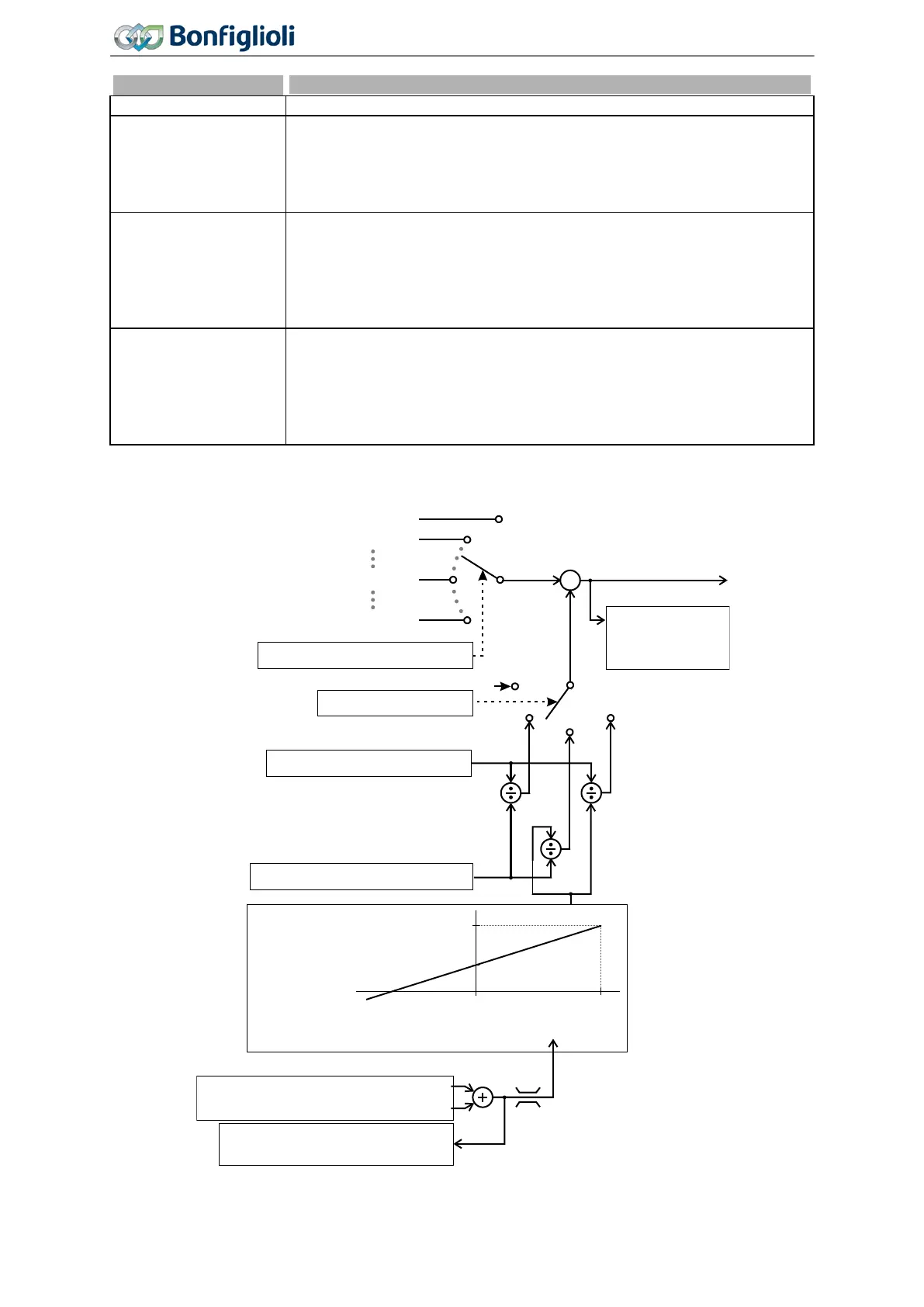
Block diagram of electronic gear:
Actual value
Reference Ramp
Frequency
283
x
Gear Factor Numerator 685
Source Master Reference 125
Operation Mode
689
Gear Factor Denominator 686
Analog factor at 100% 687
Analog factor at 0% 688
Reference Percentage Source 1 476
Reference Percentage Source 2 494
Reference percentage value
Reference percentage value
0% 100%
Actual value
Reference Percentage Value 229
0
0
1
1
2
288
3
2504
Ramp output
Fixed Frequency 1
PLC-Output Frequency 4
Repetition Frequency Input
0
300%
-300%
164
Operating Instructions
Agile
06/2013 Reference Values

 Loading...


