Parameter descriptions
7.6.2.1.3 Monitoring of analog input signal
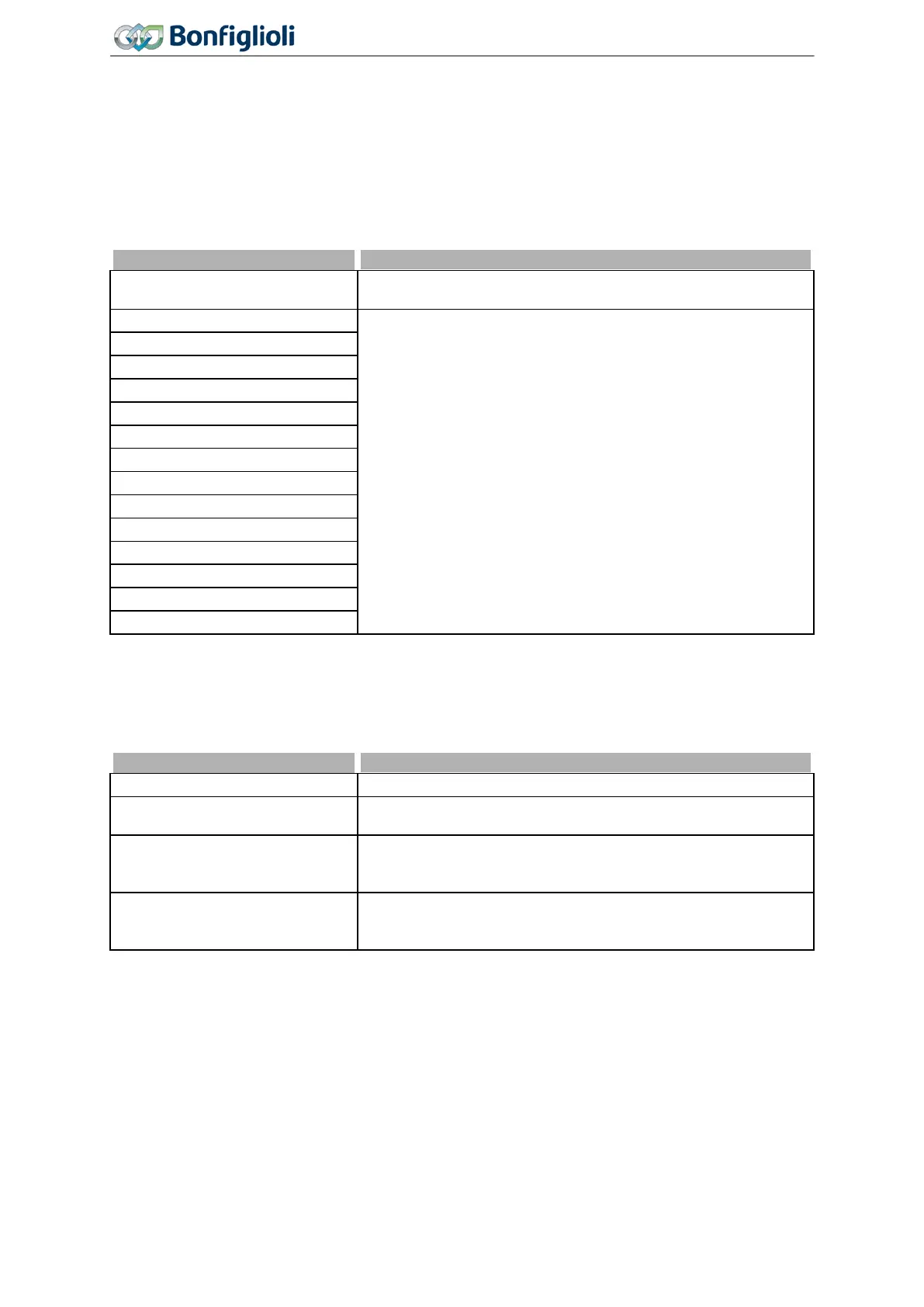
561 Filter time constant
The time constant of the filter for the analog reference value can be set via the parameter
Filter time
constant
561. The time constant indicates the time during which the input signal is averaged by
means of a low pass filter, e.g. in order to eliminate fault effects.
The setting range is between 0 ms and 5000 ms in 15 steps.
0 -
Time constant 0 ms
Filter deactivated – The analog reference value is forwarded
unfiltered.
2 -
Time constant 2 ms
Filter activated – averaging of the input signal via the set value
of the filter time constants.
4 -
Time constant 4 ms
8 -
Time constant 8 ms
16 -
Time constant 16 ms
32 -
Time constant 32 ms
64 -
Time constant 64 ms
128 -
Time constant 128 ms
4000 -
Time constant 4000 ms
5000 -
Time constant 5000 ms
563 Error/Warning Behaviour
For monitoring the analog input signal, an operation mode can be selected via parameter
Er-
ror/Warning Behaviour
563.
Error/Warning Behaviuor 563
0 - Off The input signal is not monitored. Factory setting.
1 - Warning < 1V/2 mA
If the input signal is lower than 1 V or 2 mA, a warning message
is issued.
2 - Shutdown < 1V/2 mA
If the input signal is lower than 1 V or 2 mA, a warning and fault
message is issued. The drive is decelerated according to stop-
3 -
Error-Switch-Off
< 1V/2 mA
If the input signal is lower than 1 V or 2 mA, a warning and fault
message is issued and the drive coasts to a standstill (stopping
Monitoring of the analog input signal is active regardless of the enable of the frequency inverter.
Operation mode 2 defines the shut-down and stopping of the drive, regardless of the setting of pa-
rameter
Operation Mode 630 for the stopping behavior. The drive is stopped according to stopping
behavior 2. If the set holding time has expired, an error message is issued. The drive can be started
again by switching the start signal on and off.
Operation mode 3 defines the free coasting of the drive (as described in stopping behavior 0), regard-
less of the setting of parameter
Operation Mode 630 for the stopping behavior.
180
Operating Instructions
Agile
06/2013 Control inputs and outputs

 Loading...


