Parameter descriptions
Note: Positive values limit the speed in clockwise direction; negative values limit the speed in anti-
clockwise direction. In example, if both values are positive (> 0 Hz), anticlockwise movement is inhib-
ited.
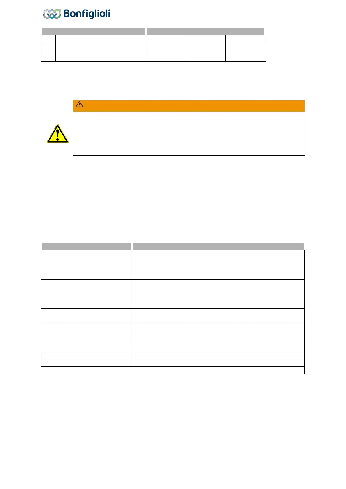
WARNING
If the torque control is activated while the actual frequency lies outside the defined
range of Frequency Upper Limit 767 and Frequency Lower Limit 768
when switching on a stopped machine or when the Flying start synchronizes), the al-
lowed frequency is driven to without ramps. The torque is only limited by the limitations
of the speed controller (current and torque). Therefore an unexpected dynamic behavior
can occur.
7.9.5.2.3 Limit Value Sources
769 Frequency upper limit source
770 Frequency lower limit
source
The frequency can be limited by setting fixed values or linking an analog input.
The assignment is done for the torque controller via
Frequency Upper Limit source 769 and
Frequency Upper Limit source 770. The frequency limits of the analog value relate
to 0 Hz and
Maximum Frequency 419. Setting a torque limit is done for
Minimum Reference Percentage 518 and Maximum Reference Percentage 519.
1 - Analog input MFI1A
The source is the multifunctional input 1 in analog operation
mode (parameter Operation Mode MFI1 452). The scaling re-
fers to 100 % =
Maximum frequency 419 for the upper limit and
0 % = 0 Hz for the lower limit.
2 - Analog input MFI2A
The source is the multifunctional input 2 in analog operation
mode (parameter Operation Mode MFI2 562). The scaling re-
fers to 100 % =
Maximum frequency 419
for the upper limit and
0 % = 0 Hz for the lower limit.
10 - Fixed limit
The selected parameter values are taken into account to limit the
speed controller. Factory setting.
708 - RxPDO1 Long1
Process data of system bus. Refer to instructions on system bus.
The value is processed as frequency.
709 - RxPDO1 Long2
Process data of system bus. Refer to instructions on system bus.
The value is processed as frequency.
Output value of a PLC function. Refer to application manual PLC.
Output value of a PLC function. Refer to application manual PLC.
Inverted values of signal sources 1 to 2502.
7.9.5.2.4 Switching over between speed control and torque control
Via the signal assigned to parameter
n-/T-Control Change-Over 164, you can switch between speed
control and torque control. See chapter 7.6.6.10 "n-/T-control changeover".
232
Operating Instructions
Agile
06/2013 Control functions

 Loading...


