EasyManua.ls Logo

BONFIGLIOLI Agile User Manual

BONFIGLIOLI Agile
360 pages
To Next Page IconTo Next Page
To Previous Page IconTo Previous Page
Page #247 background image
Parameter descriptions
Multiple motor operation
Parameter Operation Mode 571 = 1 or 11, (101 or 111).
In multiple motor operation, it is assumed that each data set is assigned to a corresponding motor.
For this, one motor and one motor circuit breaker are assigned to each data set. In this operation
mode, the rated values of the active data set are monitored. The current output current of the fre-
quency inverter is only taken into account in the motor circuit breaker activated by the data set. In
the motor circuit breakers of the other data sets, zero current is expected, with the result that the
thermal decay functions are taken into account. In combination with the data set changeover, the
function of the motor circuit breakers is similar to that of motors connected alternately to the mains
with their own circuit breakers.
Single motor operation
Parameter Operation Mode 571 = 2 or 22, (102 or 122).
The internal state of the motor circuit breaker is stored reset stable. These settings are to be used for
short-time time mains shut downs. This way the motor protection is considered correctly also in appli-
cations where a short mains power off or a shutdown orccurs.
Reset stable
Parameter Operation Mode 571 = 101, 102, 111 or 122.
The internal state of the motor protection switch is latched reset stable. These be used when regularly
short mains interruptions occur. This way the motor protection correctly for short mains failures or
short shut downs of the application.
In settings 101, 102, 111 and 112 of
Operation Mode 571 the same values should be set
in all data sets.
572 Frequency Limit
The motor protection, especially of self-ventilated motors is improved by an adjustable frequency
limit. Percentage reference is the rated frequency.
Parameters
Setting
No.
Description
Min.
Max.
Fact. sett.
572 Frequency Limit 0% 300% 0%
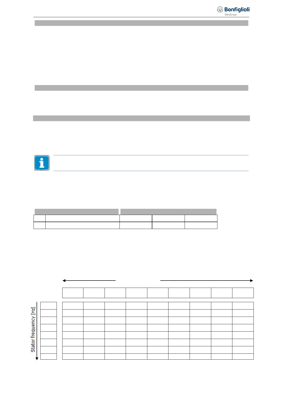
In calculation the tripping time the measured output current in operating points below the frequency
limit is evaluated by a factor between 1 and 2. The determination of this factor is a function of the sta-
tor frequency. The increased thermal load of self-ventilated motors in the lower speed range is there-
fore considered.
The table shows in extracts factors for motor rated frequency 50Hz.
Frequency limit 572
300%
200%
150%
100%
80%
60%
40%
20%
10%
0
200%
200%
200%
200%
200%
200%
200%
200%
200%
5
188%
182%
177%
168%
162%
153%
139%
114%
100%
10
177%
168%
160%
147%
139%
129%
114%
100%
100%
20
160%
147%
137%
122%
114%
106%
100%
100%
100%
30
147%
132%
122%
109%
103%
100%
100%
100%
100%
50
129%
114%
106%
100%
100%
100%
100%
100%
100%
100
106%
100%
100%
100%
100%
100%
100%
100%
100%
150
100%
100%
100%
100%
100%
100%
100%
100%
100%
247
Special functions 06/2013 Operating Instructions
Agile

Table of Contents

Other manuals for BONFIGLIOLI Agile

Question and Answer IconNeed help?

Do you have a question about the BONFIGLIOLI Agile and is the answer not in the manual?

BONFIGLIOLI Agile Specifications

General IconGeneral
Fieldbus CommunicationCANopen, Modbus RTU
Cooling MethodNatural convection
Relative Humidity5% to 95% (non-condensing)
Enclosure RatingIP20
ProtectionOvervoltage, Overtemperature

Summary

General Information about the Documentation

Documentation Overview

Details available manuals like Quick Start Guide, Operating Instructions, and Application Manual for system setup.

Warranty and Liability Information

Outlines the manufacturer's warranty terms and limitations of liability for product use.

Obligation, Copyright, and Storage

Covers user obligations, copyright information, and proper storage of the documentation.

General Safety Instructions and Information on Use

Terminology and Safety Roles

Defines key roles such as Operator, Qualified Staff, and Expert for safe operation.

Designated Use and Misuse

Specifies the intended application and potential hazards associated with misuse.

Residual Risks and Safety Signs

Identifies typical residual hazards and emphasizes compliance with safety signs.

Warning Information and Symbols

Explains hazard classes, symbols, and prohibition signs used in the manual for safety.

Operator Responsibilities and Guidelines

Outlines operator responsibilities, plant documentation, and general work safety.

Organizational Measures

Covers training, third-party product use, transport, storage, and electrical connections.

Device Overview

Inverter Type and Warning Signs

Details how to identify the inverter model and interpret warning labels on the device.

Type Designation and Components

Explains the device's type designation system and provides an overview of its components.

Software Version Identification

Describes the location and method for identifying the inverter's software version.

Mechanical Installation

Installation Safety and Guidelines

Covers essential safety precautions, mounting distances, and installation restrictions for the inverter.

Installation Sizes and Dimensions

Provides specific dimensions and mounting details for different inverter sizes (Size 1, 2, 3).

Electrical Installation

Electrical Installation Safety and Best Practices

Emphasizes safety measures, grounding, and connection conditions for electrical installation.

EMC Information and Cable Shielding

Details measures for Electromagnetic Compatibility (EMC), including cable shielding and bonding.

Mains and Motor Connection Procedures

Explains the correct procedures for connecting the mains supply and the motor to the inverter.

Commissioning

Operator Panel Functions and Menu Navigation

Describes the operator panel's buttons, menus, and navigation for parameter settings.

First Commissioning Procedures

Guides users through the initial setup for asynchronous and synchronous motors.

Parameter Descriptions

Inverter Data and Machine Data

Details parameters related to serial number, software version, and motor specifications.

Operational Behavior Settings

Covers parameters for controlling start, stop, direction, speed, and operational modes.

Error and Warning Handling

Explains how the inverter manages errors and warnings, including message codes and diagnosis.

Reference Values and Ramps

Defines how reference values like frequency and percentage are set, scaled, and ramped.

Control Inputs and Outputs Configuration

Details the configuration and functions of digital and analog inputs/outputs and their signals.

Energy Saving

Energy Saving Function Configuration

Explains how to set up the energy saving function for optimized motor power consumption.

Standby Mode Options

Describes settings for reducing power consumption when the inverter is idle or in standby.

Actual Values

Actual Values of Frequency Inverter

Lists real-time values from the frequency inverter, like DC-link voltage, modulation, and frequency.

Actual Values of Machine

Provides actual values related to the connected motor, such as stator frequency, current, and torque.

Service

Regular Service Work and Cleaning Procedures

Outlines recommended maintenance tasks and cleaning instructions for the frequency inverter.

Service Interval Monitoring

Explains how to monitor and reset service intervals for components like DC-link and fans.

Technical Data

General Technical Data and Compliance

Covers CE conformity, EMC directives, UL approval, and general environmental conditions.

Device Data by Model and Power

Lists specific technical data, dimensions, and ratings for different Agile series models and power ratings.

OPTIONS

Safety Precautions for Options

Highlights safety considerations when installing and using optional components.

Shield Sheets for EMC Compliance

Details the installation of optional shield sheets for control and motor cables to ensure EMC conformity.

Input Filters and Line Chokes

Explains the types of input filters and line chokes for EMC suppression and their installation requirements.

Assembly Variants and Mounting Options

Describes different assembly options like feed-through, cold plate, vibration-proof, and DIN rail mounting.

ERROR PROTOCOL

Error List and Messages

Provides a comprehensive list of error codes, their meanings, and initial troubleshooting steps.

Error Environment and Troubleshooting

Details actual values recorded at the time of a fault for diagnostic purposes and troubleshooting guidance.

OPERATIONAL AND ERROR DIAGNOSIS

Status of Digital Signals and Controller Status

Explains how to interpret the status of digital signals and controller codes for operational diagnosis.

Warning Status and Application Warnings

Describes how to interpret warning status codes and application-specific warnings for proactive issue identification.

PARAMETER LIST

Actual Values (Menu Actual)

Lists all actual values that can be read from the frequency inverter for monitoring and diagnostics.

Parameters (Menu PARA)

Provides a comprehensive list of all settable parameters, their units, ranges, and chapter references.

Related product manuals