1 689 989 300 2020-03-24| Robert Bosch GmbH
76 | EPS 118 | Operationen
1
2
3
4
6
7
5
458900-23_Pal
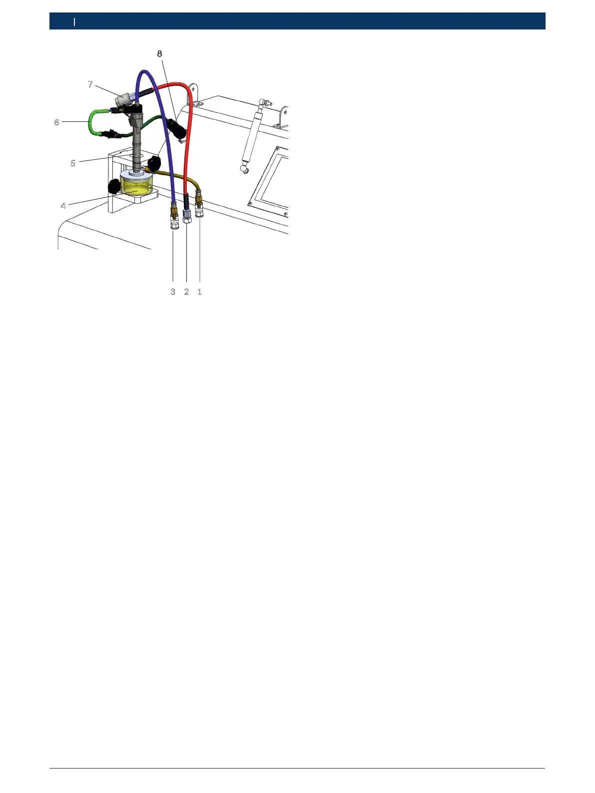
Fig. 37: Schematic diagram of the CRI connection
1 Injected fuel quantity test connection
2 High-pressure connection
3 Test connection for return quantity (CRI/CRIN/piezo CRI)
4 Injection chamber
5 Injector
6 Adapter cable
7 Connection adapter for CRI/CRIN and piezo CRI
8 Connection cable 1684448333
1)
1)
Only necessary for connecting non-Bosch CRI adapter cables.
Included in accessory set 1 687 010 718 (non-Bosch CRI
accessory set).
i For non-Bosch CRIs, accessory set 1 687010718
is required (optional accessories).
i The prerequisites to be observed when checking
and adjusting the Bosch piezo CRI can be found in
the test instructions for piezo CRI in ESI[tronic]2.0.
These test instructions do not form part of the
scope of delivery. ESI[tronic] 2.0 can not be ins-
talled on the EPS 118.
Procedure:
1. Clean the CRI/CRIN, piezo CRI (see sec. 7.3).
i When the CRIN has internal connections, the CRIN
must be installed in the test adapter before clam-
ping (see sec. 5.4.8).
2. Clamp the CRI/CRIN, piezo CRI (Fig. 37, item5)
(see sec. 5.4.6).
! Do not connect the high-pressure hose assembly to
the injector. Always use the connection adapter for
CRIs/CRINs and piezo CRIs when connecting the
high-pressure hose assembly to the injector.
Follow the proper connection sequence (see sec.
5.4.7).
! The connection adapter for CRI/CRIN and piezo CRI
must be tightened to a torque of 25Nm to 30Nm.
If the connection between the connection adapter
and the injector is leaking, the screw connection is
not to be re-tightened. In the event of a leak, unfas-
ten the connection again, clean the sealing surface
and re-connect the connection adapter applying the
correct tightening torque.
3. Connect adapter M12 — M14 (Fig. 6, item2) to
the high-pressure connection of the injector (only
necessary when the high-pressure connection has
threads measuring M14x1.5).
Tightening torque 25 — 30Nm
4. Connect the connection adapter (Fig. 37, item7)
to the high-pressure connection of the CRI/CRIN/
piezo CRI or adapter M12 — M14.
Tightening torque 25 – 30Nm.
! The smallest permissible bending radius of the
high-pressure hose assembly is 90mm.
! The high-pressure hose assembly must not come
into contact with the protective hood during opera-
tion.
5. Connect the high-pressure hose assembly to the
high-pressure connection (Fig. 37, item2).
Tightening torque 25 – 30Nm.
6. Connect the other end of the high-pressure hose
assembly to the connection adapter (Fig. 37,
item7).
Tightening torque 25 – 30Nm.
 Loading...