1 689 989 300 2020-03-24| Robert Bosch GmbH
Operation | EPS 118 | 77 en
i For certain CRIN from Bosch, the "CRIN adapter
with check valve" (Fig. 9, item 9) must be used as
well. It is inserted into the test connection for the
return quantity (CRI/CRIN, piezo CRI; see Fig. 3,
item3) prior to starting the test and then connec-
ted to the hose assembly 1684 462570 (Fig. 9,
item 1). Which CRIN needs the adapter is displayed
in the EPS 118 software after the CRIN is selected.
! If the CRIN adapter with check valve 1683350904
(Fig. 9, item 9) is not used in accordance with
the instructions or is connected incorrectly, e. g.
directly to the CRIN, a faulty measurement results,
leading to an incorrect evaluation of the CRIN.
7. Connected the injector-specific hose assembly
(seesection5.4.9) to the "Test connection for
return quantity" (Fig. 37, item3) or to the CRIN
adapter with check valve 1683350904.
8. Connect the other end of the injector-specific hose
assembly (see sec. 5.4.9) to the return of the
CRI/CRIN or piezo CRI.
i Only connect third-party CRIs to port X7 of the
EPS 118 in conjunction with connection cable
1684448333 (Fig. 37, item 8) and with the
correct adapter cable (see section 5.4.13). For
Denso CRIs / piezo CRIs, use adapter cable
1684463618.
9. Connect the injector-specific adapter cable
(seesec. 5.4.10 or sec. 5.4.13) to socket X7
(Fig.3, item10) of the EPS 118.
10. Connect the other end of the injector-specific adap-
ter cable (seesec. 5.4.10 or sec. 5.4.13) to the
CRI/CRIN or piezo CRI.
! Route the injector-specific adapter cable such that
it does not come into contact with the hot hose
assemblies.
11. Close the protective hood.
12. Continue the test in sec. 7.9.
7.7 Program description
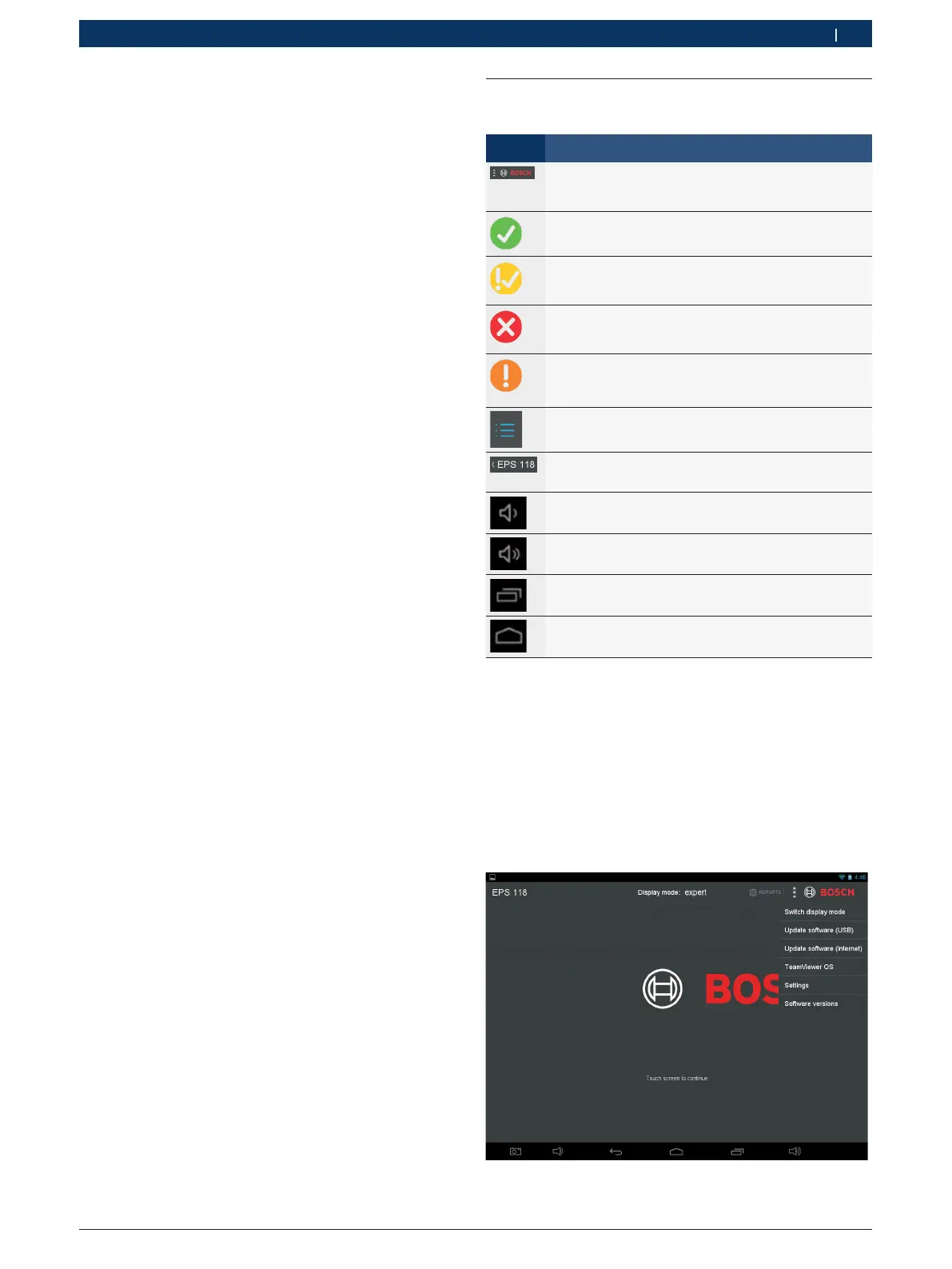
7.7.1 Key to symbols
Icon Description
"Options" button
Provides different options depending on the current
screen.
"Passed" icon
Indicates a positive test result.
Pass on Limits" icon
Indicates a positive test result just within the limits.
"Not passed" icon
Indicates a negative test result, e. g. because of ex-
cessive leakage in the return from the injector.
"Error" icon
Compressed air supply inadequate (for remedy, see
section 7.9).
"Test steps" icon
Hides and displays the test steps.
"Back" button
Navigate to the previous screen.
"Quieter" button
Decreases the volume.
"Louder" button
Increases the volume.
"Open applications" button
Displays all open applications.
"Home" button
The home screen is displayed.
7.7.2 Home Screen (Fig. 38)
The start screen appears after logging in. The fol-
lowing functions can be executed:
R Touch the Bosch logo to open the injector selection
screen (see sec. 7.7.1).
R "Log" button; select to view previously generated
logs.
R "Options" button; select to access different options
like the settings.
Fig. 38: Home Screen
 Loading...