5-119
Confidential
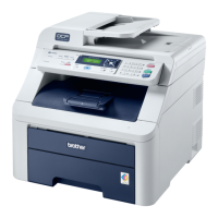
(2) Remove the four Taptite cup S M3x6 SR screws, and then remove the LED PCB cover
and Insulation sheet B from the Sub frame ASSY.
Fig. 5-135
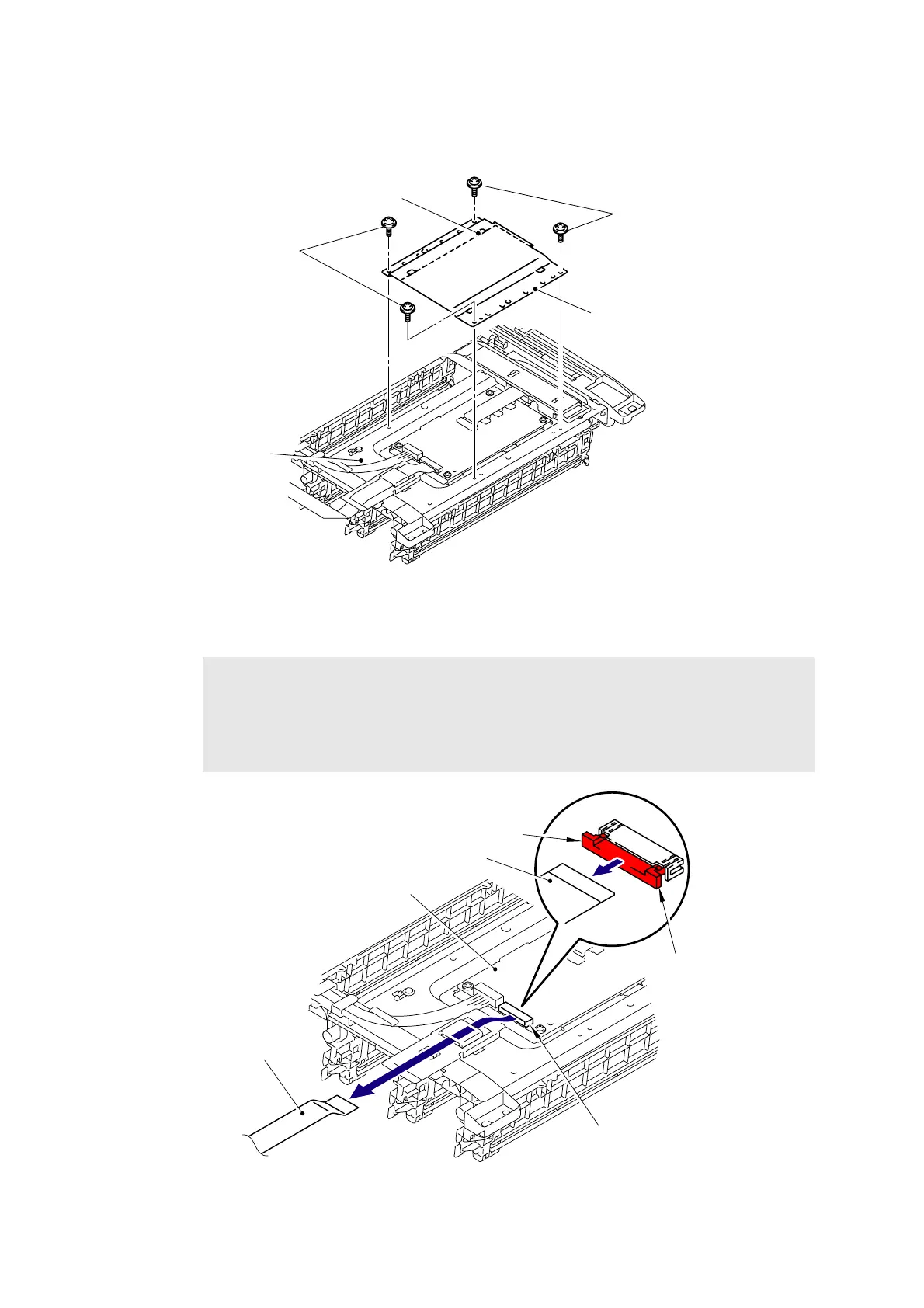
(3) Disconnect the FFC harness:MAIN-LED CTL (CN5) from the LED head control PCB ASSY.
Fig. 5-136
Note:
- After disconnecting the flat cable(s), check that each cable is not damaged at its end
or short-circuited.
- When connecting the flat cable(s), do not insert it at an angle. After insertion, check
that the cable is not at an angle.
Taptite cup S M3x6 SR
Sub frame ASSY
LED PCB cover
Taptite cup S M3x6 SR
Insulation sheet B
LED head control PCB ASSY
FFC harness:MAIN-LED CTL
CN5
FFC harness:MAIN-LED CTL
Lock
Lock
 Loading...