5-138
Confidential
8.55 Engine PCB ASSY
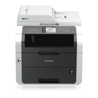
(1) Disconnect the eleven connectors (CN1, CN2, CN4, CN6, CN7, CN8, CN9, CN10, CN11,
CN14, CN15) and one flat cable (CN3) from the Engine PCB ASSY.
Fig. 5-159
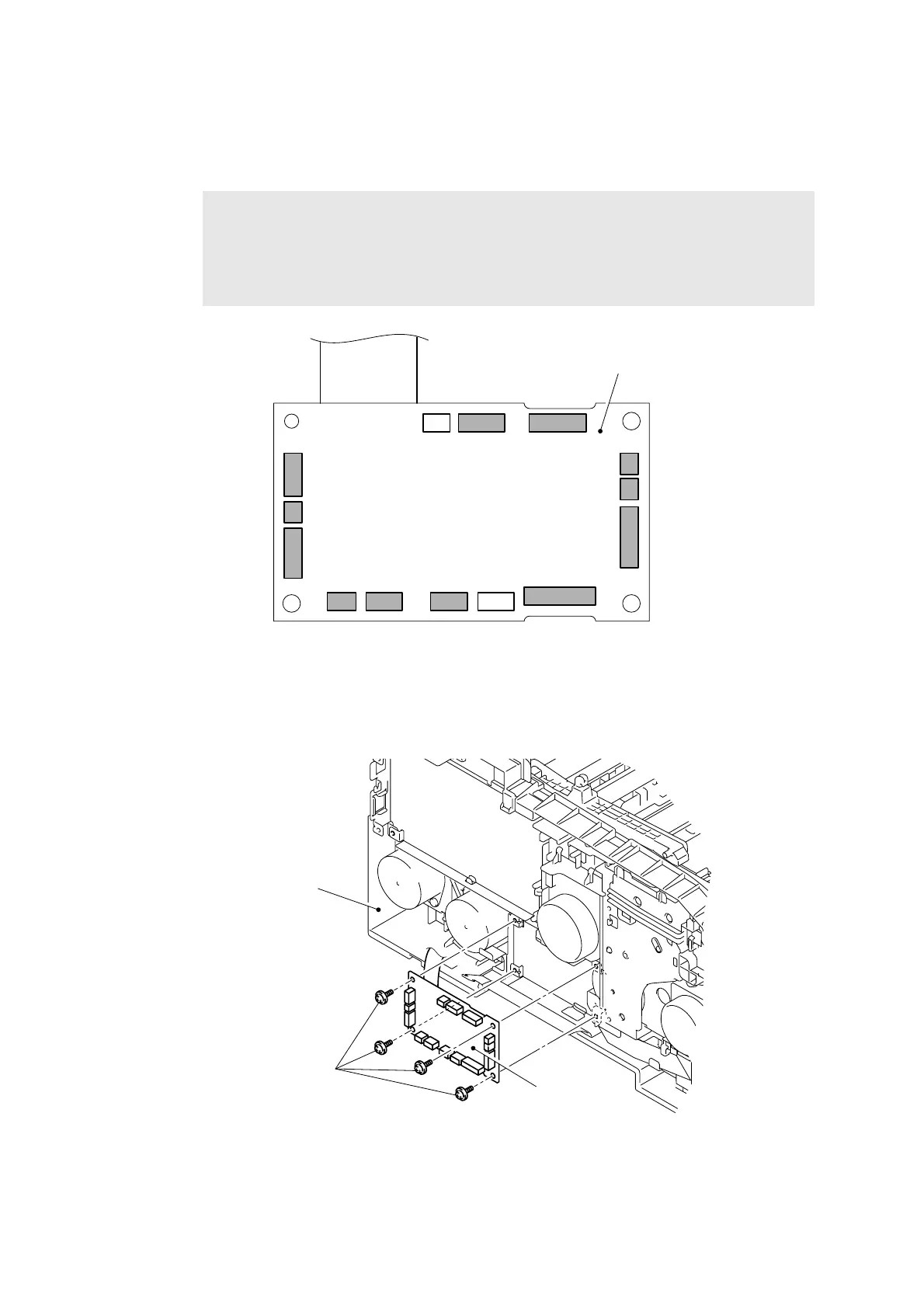
(2) Remove the four Taptite cup S M3x6 SR screws, and then remove the Engine PCB ASSY
from the Side frame L.
Fig. 5-160
Note:
- After disconnecting the flat cable(s), check that each cable is not damaged at its end
or short-circuited.
- When connecting the flat cable(s), do not insert it at an angle. After insertion, check
that the cable is not at an angle.
CN11
CN15CN14CN13
CN1
CN2
CN3
CN10
CN9
CN8 CN7 CN6 CN5
CN4
Engine PCB ASSY
Engine PCB ASSY
Taptite cup S M3x6 SR
Side frame L
<Left side>

 Loading...