5-195
Confidential
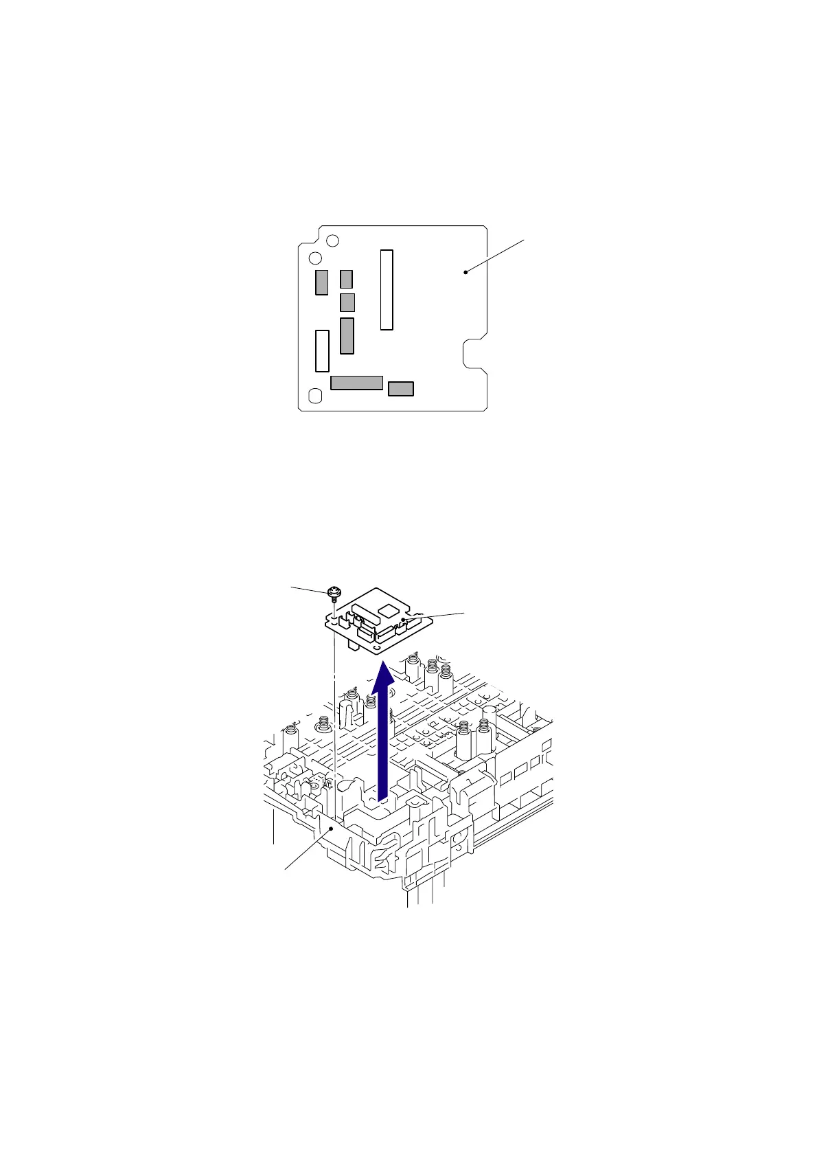
8.85 HVPS Control PCB ASSY
(1) Disconnect the six Connectors (CN1, CN4, CN5, CN8, CN9, CN10) from the HVPS
control PCB ASSY.
Fig. 5-255
(2) Remove the Taptite pan (S/P W) B M3x10 screw, and then remove the HVPS control PCB
ASSY from the Side frame R.
Fig. 5-256
CN1
CN8
CN3
CN10
CN9
CN7
CN5
CN4
HVPS control PCB ASSY
HVPS control PCB ASSY
Taptite pan (S/P W) B M3x10
Side frame R
 Loading...