5-165
Confidential
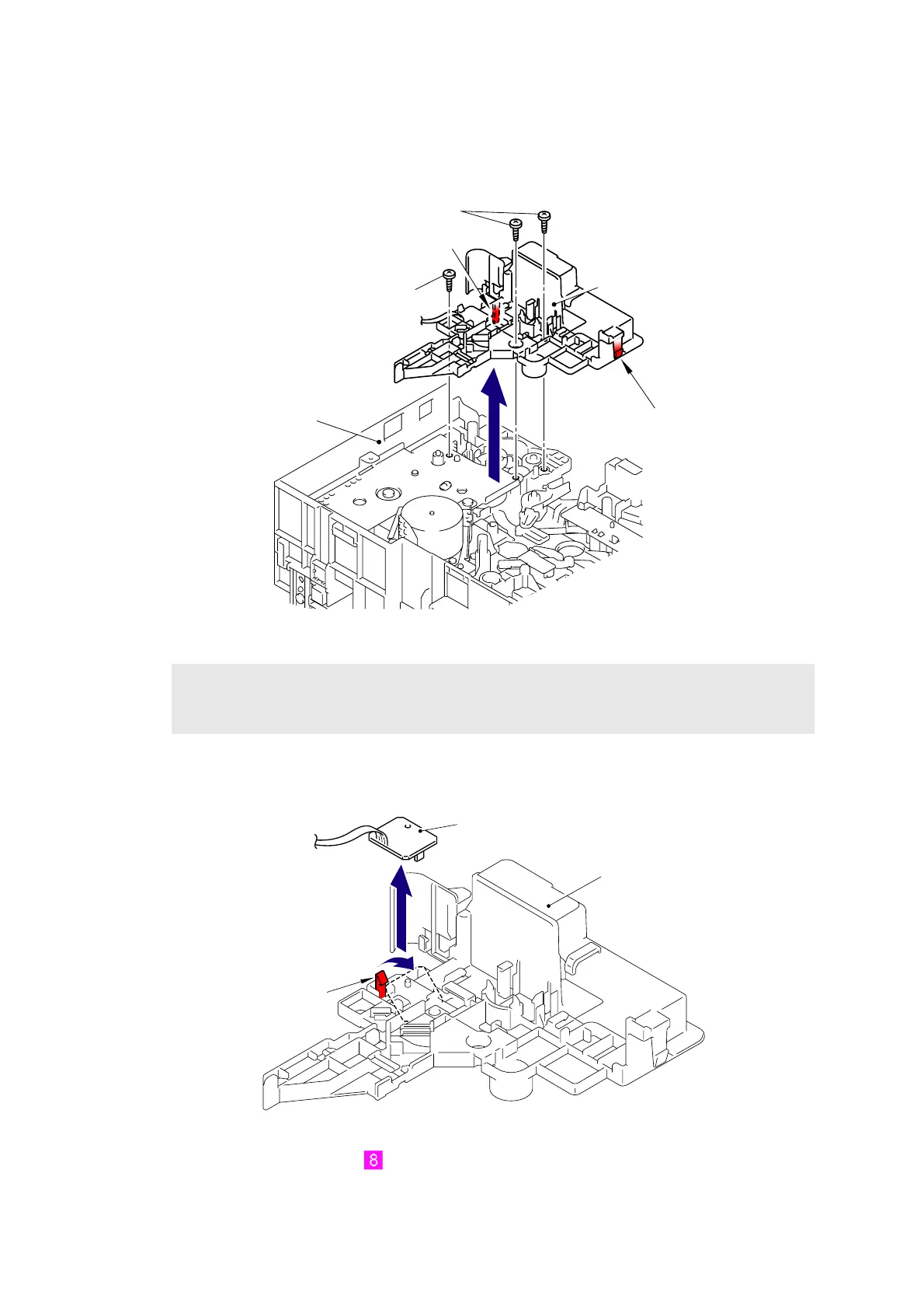
8.70 Fuser/Eject Drive Motor Sensor PCB ASSY
(1) Remove the three Taptite bind B M4x12 screws, and then remove the Eject gear cover
from the Side frame L.
Fig. 5-206
(2) Release the Hook to remove the Fuser/eject drive motor sensor PCB ASSY from the
Eject gear cover.
Fig. 5-207
Harness routing: Refer to “ Fuser/Eject Drive Motor, Fuser/Eject Drive Motor Sensor PCB
ASSY.”
Note:
Be careful when changing the setup condition of the main body with the left side up while
the Eject gear cover is removed because the gear may fall off.
Taptite bind B M4x12
Side frame L
Eject gear cover
Taptite bind B M4x12
Hook
Hook
Hook
Eject gear cover
Fuser/eject drive motor sensor PCB ASSY
2b
2a
 Loading...