5-137
Confidential
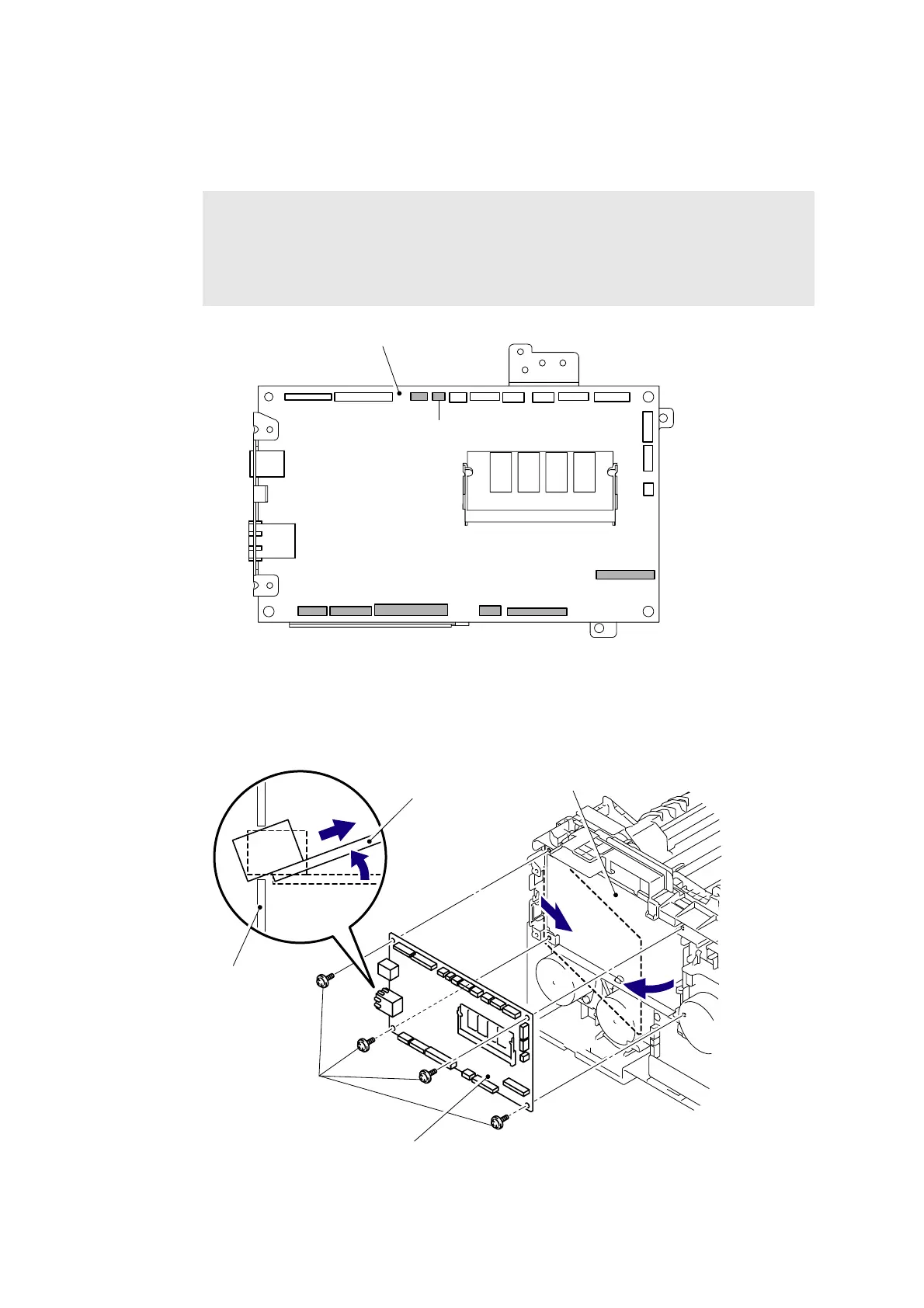
8.54 Main PCB ASSY
(1) Disconnect the seven Connectors (CN10, CN15, CN17, CN18, CN19, CN22, CN23) and
one flat cable (CN5) from the Main PCB ASSY.
Fig. 5-157
(2) Remove the four Taptite cup S M3x6 SR screws, and then remove the Main PCB ASSY
from the Main PCB shield plate.
Fig. 5-158
Note:
- After disconnecting the flat cable(s), check that each cable is not damaged at its end
or short-circuited.
- When connecting the flat cable(s), do not insert it at an angle. After insertion, check
that the cable is not at an angle.
CN24
CN20
CN27
CN26
CN23
CN22
CN19
CN15
CN10
CN1
CN2
CN3
CN18
CN17
CN16
CN14
CN13
CN11
CN8
CN5
CN6
Main PCB ASSY
Main PCB shield plate
Main PCB ASSY
Main PCB shield plate
Main PCB ASSY
Taptite cup S M3x6 SR
2a
2b
2a
2b
<Left side>
 Loading...