Apr. 2007
2
-35
DSC48
417W254A
417W253A
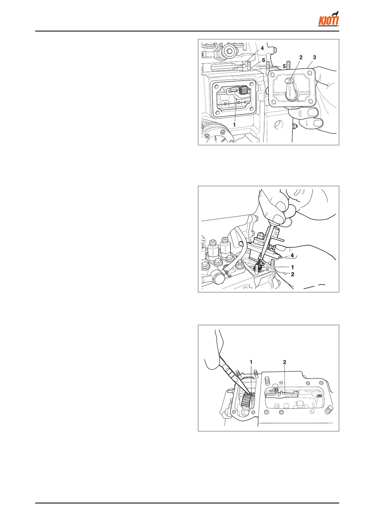
(1) Fork lever 1 (4) Control rack pin
(2) Engine stop lever (5) Groove
(3) Injection pump cover (6) Shim
(1) Governor spring 1 (3) Fork lever 2
(2) Governor spring 2 (4) Governor lever
B. TIMING GEARS AND CAMSHAFTS
► INJECTION PUMP
1. Remove the injection pump cover (3) with the engine
stop lever (2).
2. Remove the injection pump.
<When reassembling>
• Apply a liquid gasket to the shim (6) and both sides of
the injection pump cover gasket before installing them.
• Install the injection pump so that its control rack pin (4)
engages with the groove (5) of the fork lever 1.
• Install the injection pump cover with the shaft of the en-
gine stop lever (2) at the right side of the protrusion of
the fork lever 1 (1).
► GOVERNOR SPRINGS AND SPEED CONTROL
PLATE
1. Separate the governor springs 1 (1) and 2 (2) from the
governor lever (4).
2. Remove the speed control plate.
3. Remove the governor springs 1 and 2 from the fork le-
ver (2).
<When reassembling>
• Fix the governor springs 1 and 2 to the fork lever 2. And
pull the springs to hook on the governor lever.
• Be careful not to drop the governor springs 1, 2 into the
gear case.
• Apply a liquid gasket to both sides of the speed control
plate gasket.
417W256A
► START SPRING
1. Remove the start spring (1) from the fork lever 1 (2).
<When reassembling>
• Be careful not to drop the start spring into the gear
case.
• Hook the start spring fi rst to the long hole, which is next
to the fork lever.
(1) Start spring (2) Fork lever 1