Programming Guide | VLT® AutomationDrive FC 360
1) Built-in brake chopper available for J1–J5.
2) Relay 2 is 2-pole for J1–J3 and 3-pole for J4–J9. Relay 2 of J4–J9 with terminals 4, 5, and 6 has the same NO/NC logic as
relay 1. Relays are pluggable in J1–J5 and fixed in J6–J7.
3) Single DC choke in J1–J5; Dual DC choke in J6–J9.
4) Switch S800 (bus terminal) can be used to enable termination on the RS485 port (terminals 68 and 69).
5) No BR for J6–J9.
6) No terminal 81, 88 and 89 for J8 and J9.
In rare cases, long control cables and analog signals could result in 50/60 Hz ground loops due to noise from mains supply cables. If this
occurs, break the shield or insert a 100 nF capacitor between shield and chassis.
The digital and analog inputs and outputs must be connected separately to the common inputs (terminal 20 and 55) of the drive to
avoid ground currents from both groups to affect other groups. For example, switching on the digital input could disturb the analog
input signal.
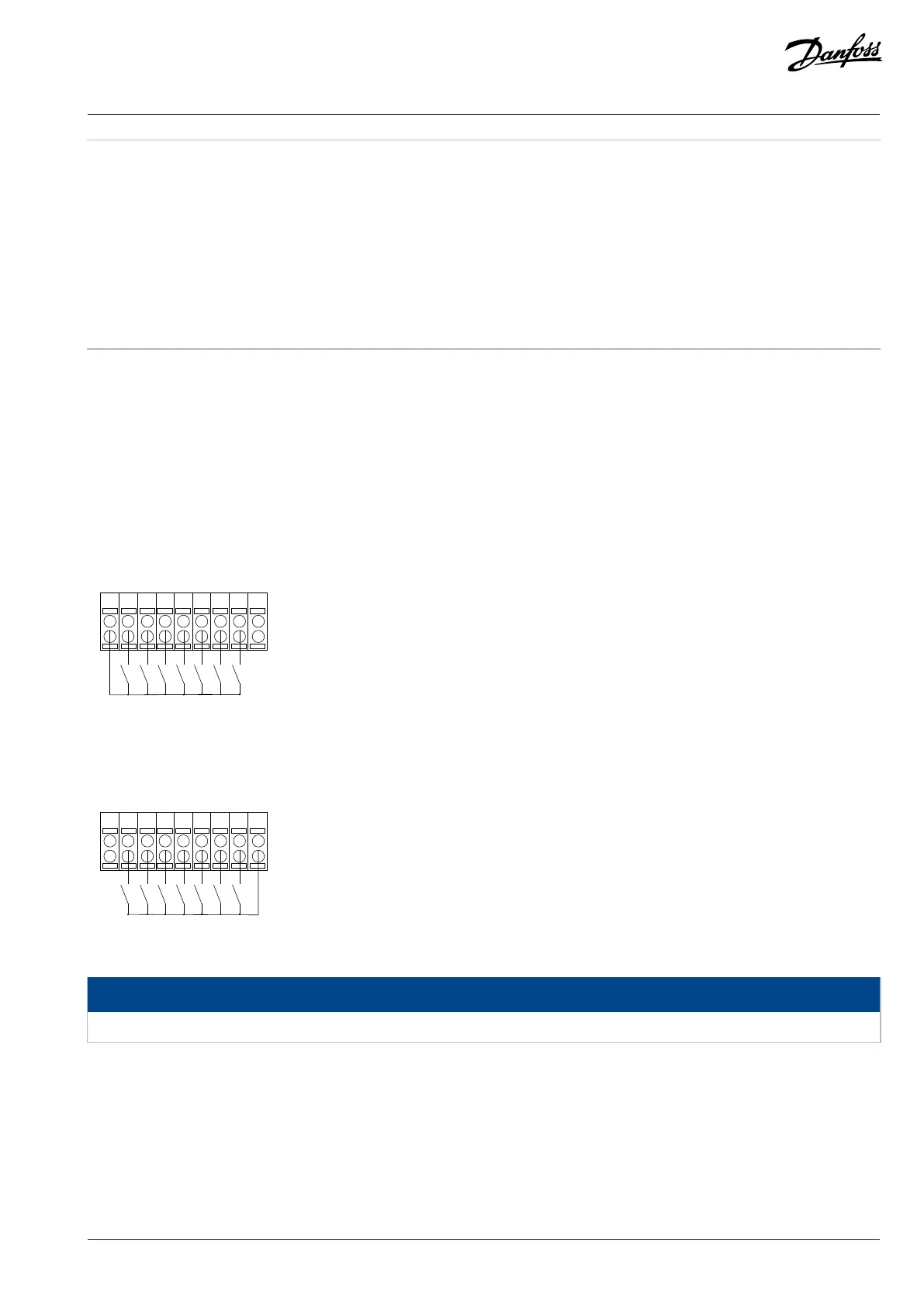
Input polarity of control terminals
Figure 2: PNP (Source) Digital Input Wiring
Figure 3: NPN (Sink) Digital Input Wiring
NOTICE
Control cables must be shielded/armored.
See the section Using Shielded Control Cables in the design guide for the correct termination of control cables.
Danfoss A/S © 2024.01 AU275649936274en-001401 / 130R0507 | 11

 Loading...


