The reset can be done in 3 ways:
l Press [Reset].
l A digital reset input.
l Serial communication/optional fieldbus reset signal.
NOTICE
After a manual reset pressing [Reset], press [Auto On] to restart the motor.
A warning precedes an alarm.
A trip lock is an action when an alarm occurs which can damage the drive or connected equipment. Power is removed from the motor. A
trip lock can only be reset after a power cycle has cleared the condition. Once the problem has been rectified, only the alarm continues
flashing until the drive is reset.
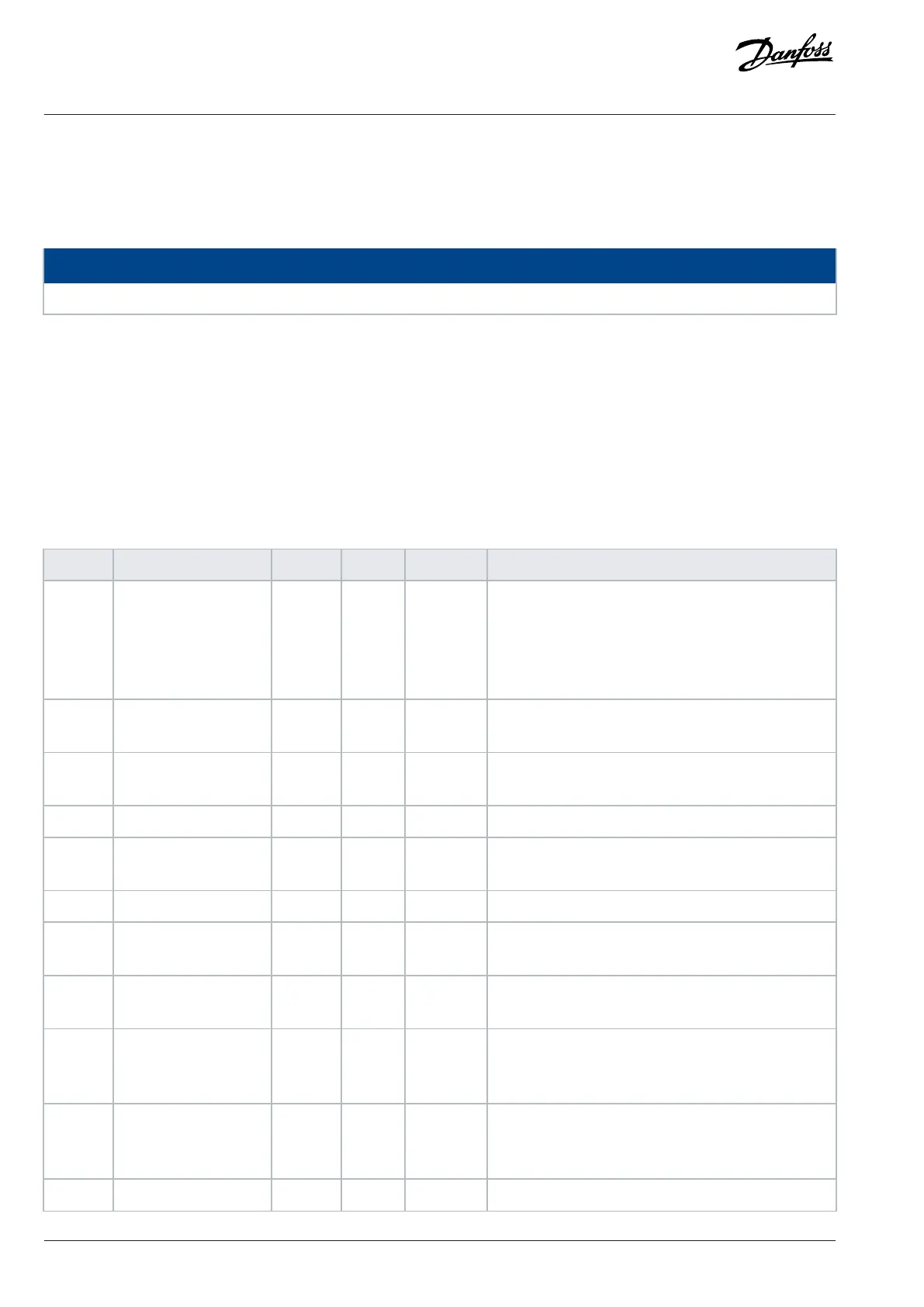
5.1.5 Warnings and Alarms Code List
The warnings and alarms are explained in the following table.
Table 25: Warnings and Alarms Code List
Number Description Warning Alarm Trip lock Cause
2 Live zero error X X – Signal on terminal 53 or 54 is less than 50% of the val-
ues set in parameter 6-10 Terminal 53 Low Voltage,
parameter 6-12 Terminal 53 Low Current, parameter 6-20
Terminal 54 Low Voltage, and parameter 6-22 Terminal
54 Low Current.
3 No motor X – – No motor has been connected to the output of the drive,
or 1 motor phase is missing.
4 Mains phase loss
1)(1)
X X X Missing phase on the supply side, or the voltage imbal-
ance is too high. Check the supply voltage.
7 DC overvoltage
(1)
X X – DC-link voltage exceeds the limit.
8 DC undervoltage
(1)
X X – DC-link voltage drops below the voltage warning low
limit.
9 Inverter overloaded X X – More than 100% load for too long.
10 Motor ETR overtemper-
ature
X X – Motor is too hot due to more than 100% load for too
long.
11 Motor thermistor
overtemperature
X X – Thermistor or thermistor connection is disconnected, or
the motor is too hot.
12 Torque limit X X – Torque exceeds value set in either parameter 4-16
Torque Limit Motor Mode or parameter 4-17 Torque Limit
Generator Mode.
13 Overcurrent X X X Inverter peak current limit is exceeded. For J1–J6 units, if
this alarm occurs on power-up, check whether power ca-
bles are mistakenly connected to the motor terminals.
14 Ground fault – X X Discharge from output phases to ground.
306 | Danfoss A/S © 2024.01 AU275649936274en-001401 / 130R0507
Programming Guide | VLT® AutomationDrive FC 360

 Loading...


