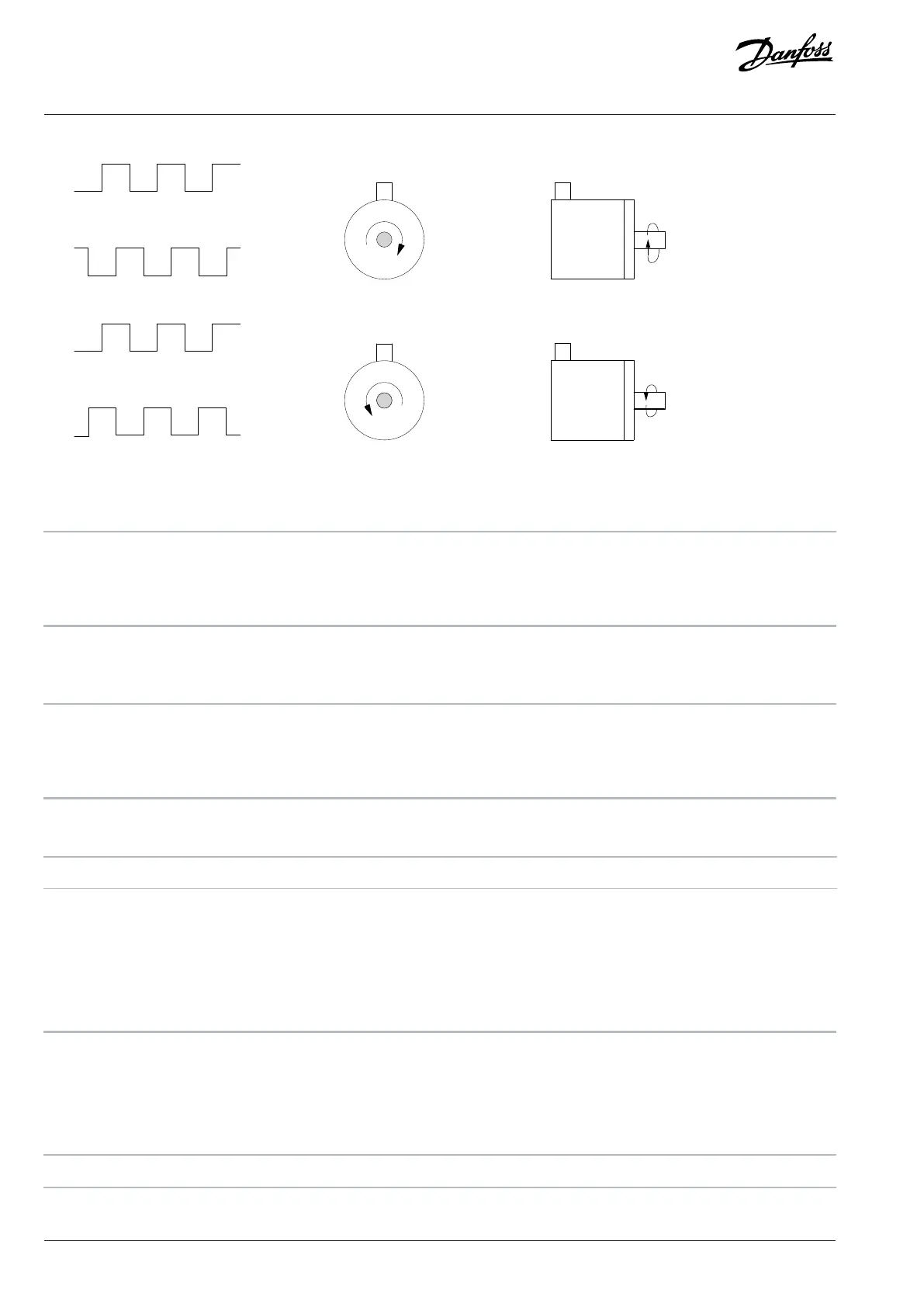
Figure 33: Encoder Rotation Direction
5-70 Term 32/33 Pulses Per Revolution
Default value: 1024 Parameter type: Range (1–4096)
Setup: All setups Conversion index: 0
Data type: Uint16 Change during operation: False
Set the encoder pulses per revolution on the motor shaft. Read the correct value from the encoder.
5-71 Term 32/33 Encoder Direction
Default value: [0] Clockwise Parameter type: Option
Setup: All setups Conversion index: –
Data type: Uint8 Change during operation: False
Change the detected encoder rotation direction without changing the wiring to the encoder.
Option Name Description
[0] Clockwise Set channel A 90° (electrical degrees)
behind channel B after clockwise rotation
of the encoder shaft.
[1] Counterclockwise Set channel A 90° (electrical degrees)
ahead of channel B after clockwise
rotation of the encoder shaft.
4.6.8 5-9* Bus Controlled
This parameter group selects digital and relay outputs via a fieldbus setting.
5-90 Digital & Relay Bus Control
Default value: 0 Parameter type: Range (0–0xFFFFFFFF)
142 | Danfoss A/S © 2024.01 AU275649936274en-001401 / 130R0507
Programming Guide | VLT® AutomationDrive FC 360

 Loading...


