3 Programming
3.1 Local Control Panel Operations
3.1.1 Local Control Panel (LCP)
The drive supports numerical local control panel (NLCP) LCP 21, graphic local control panel (GLCP) LCP 23. This chapter describes the
operations with LCP 21 and LCP 23.
The drive can also be programmed from the VLT® Motion Control Tool MCT 10 on PC via RS485 com-port. This software can be ordered
using code number 130B1000 or downloaded from the Danfoss website: https://www.danfoss.com/en/service-and-support/downloads/
dds/vlt-motion-control-tool-mct-10/#tab-overview.
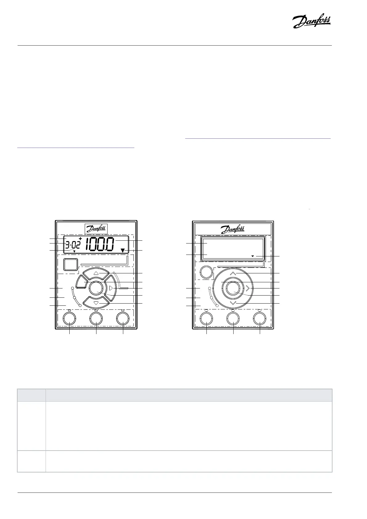
The local control panel is divided into 4 functional sections.
l A. Display.
l B. Menu key.
l C. Navigation keys.
l D. Operation keys and indicator lights (LEDs).
6
7
8
10
11
12
13
9
14
15 16
LCP 23
3-02 Minimum Referenc
e
0.000
Figure 9: Local Control Panel (LCP 21 and LCP 23)
Functional Section A: Display
Table 3: Display Function
Number Function
1 The setup number shows the active setup and the edit setup.
• For LCP 21: The setup number shows the active setup and the edit setup. If the same setup acts as both active and edit
setup, only that setup number is shown (factory setting).
• For LCP 23, the setup number is shows in the upper right corner in the status mode. For example, “1(2)” means the
active setup is "1" and the editing setup is "2".
2 • LCP 21 shows only parameter number.
• LCP 23 shows both parameter number and name.
20 | Danfoss A/S © 2024.01 AU275649936274en-001401 / 130R0507
Programming Guide | VLT® AutomationDrive FC 360

 Loading...


