Programming Guide | VLT® AutomationDrive FC 360
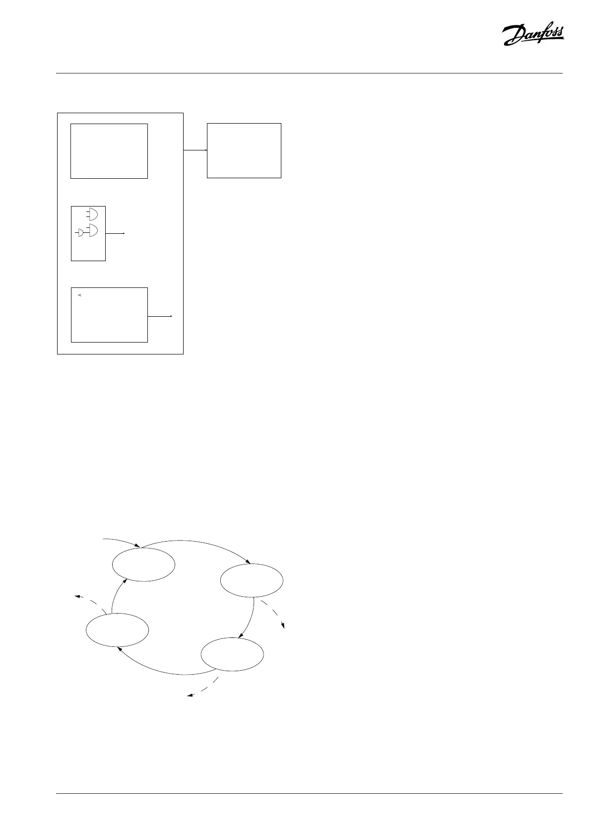
Par. 13-11
Comparator Operator
Par. 13-43
Logic Rule Operator 2
Set Do X low
Select setup 2
. . .
Torque limit
Digital input X 30/2
. . .
=
TRUE longer than..
. . .
. . .
Figure 39: Smart Logic Control (SLC)
Events and actions are each numbered and linked in pairs (states). This means that when the 1st event is fulfilled (becomes true), the
1st action is executed. After this, the conditions of the 2nd event are evaluated and if evaluated true, the 2nd action is executed, and so
on. Only 1 event is evaluated at any time. If an event is evaluated as false, nothing happens (in the SLC) during the current scan interval
and no other events are evaluated. This means that when the SLC starts, it evaluates the 1st event (and only the 1st event) in each scan
interval. Only when the 1st event is evaluated true, the SLC executes the 1st action and starts evaluating the 2nd event. It is possible to
program 1–20 events and actions.
When the last event/action has been executed, the sequence starts over again from the 1st event/action. The following illustration shows
an example with 3 events/actions:
Stop
event P13-02
Stop
event P13-02
Figure 40: Events and Actions
Danfoss A/S © 2024.01 AU275649936274en-001401 / 130R0507 | 211

 Loading...


