Programming Guide | VLT® AutomationDrive FC 360
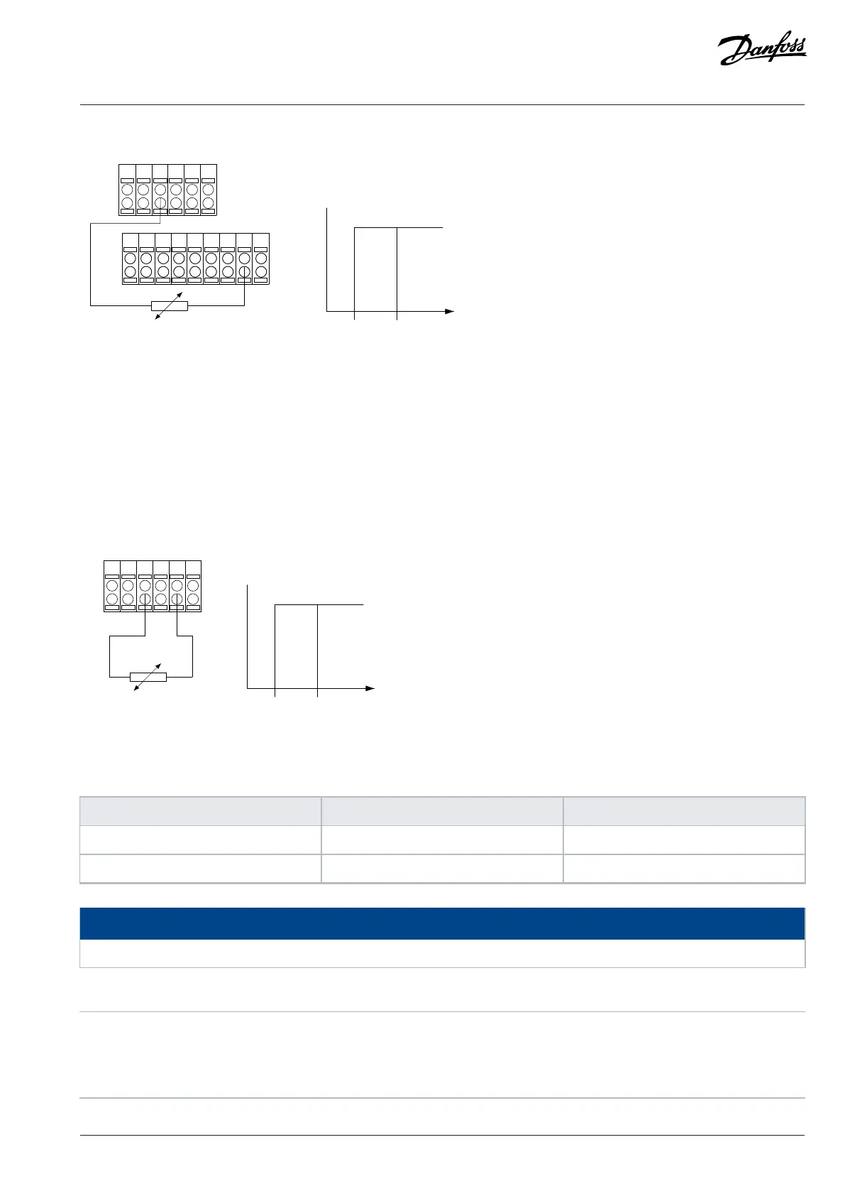
PTC / Thermistor
R
OFF
ON
< 800 Ω
+ 10 V
e30bv183.10
> 2.9 kΩ
Figure 19: PTC Thermistor Connection - Digital Input
Using an analog input and 10 V as supply:
Example: The drive trips when the motor temperature is too high.
Parameter setup:
l Set parameter 1-90 Motor Thermal Protection to [2] Thermistor Trip.
l Set parameter 1-93 Thermistor Source to [2] Analog Input 54.
Figure 20: PTC Thermistor Connection - Analog Input
Table 13: Threshold Cut Out Values
Input digital/analog Supply voltage Threshold cut out values
Digital 10 V <800 Ω - 2.9 kΩ
Analog 10 V <800 Ω - 2.9 kΩ
NOTICE
Check that the selected supply voltage follows the specification of the used thermistor element.
1-93 Thermistor Source
Default value: [0] None Parameter type: Option
Setup: All setups Conversion index: –
Data type: Uint8 Change during operation: False
Danfoss A/S © 2024.01 AU275649936274en-001401 / 130R0507 | 77

 Loading...


