AS Autosampler Operator’s Manual
194 Doc. 065051-03 1/08
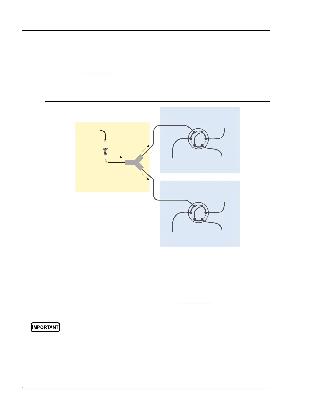
2. Connect one of the lines from the Y-connector to port S (5) on the
injection valve of the first chromatography system module (see
Figure B-27
).
3. Connect the other line to port S (5) on the injection valve of the
second chromatography system module.
4. Route the green waste lines connected to port W (6) on each injection
valve through the side slots to the AS drip tray. Insert one line into the
small round opening in the tray (see Figure B-23
). Insert the other
line about 12 mm (1/2 in) into the large drain opening in the tray.
Figure B-27. Injection Valve Connections for Simultaneous Injection:
Valves Installed in Two Chromatography System Modules
Make sure the injection valve waste lines are not elevated above the
injection valves at any point between the valves and the AS drip tray.
AS Needle
Seal Line
To Waste
To Column
From Pump
Chromatography System Module #2
AS Autosampler
Sample In
W
L
P
C
L
S
To Waste
To Column
From Pump
Chromatography System Module #1
W
L
P
C
L
S