Doc. 065051-03 1/08 317
E • TTL and Relay Control
E.1 TTL and Relay Connections
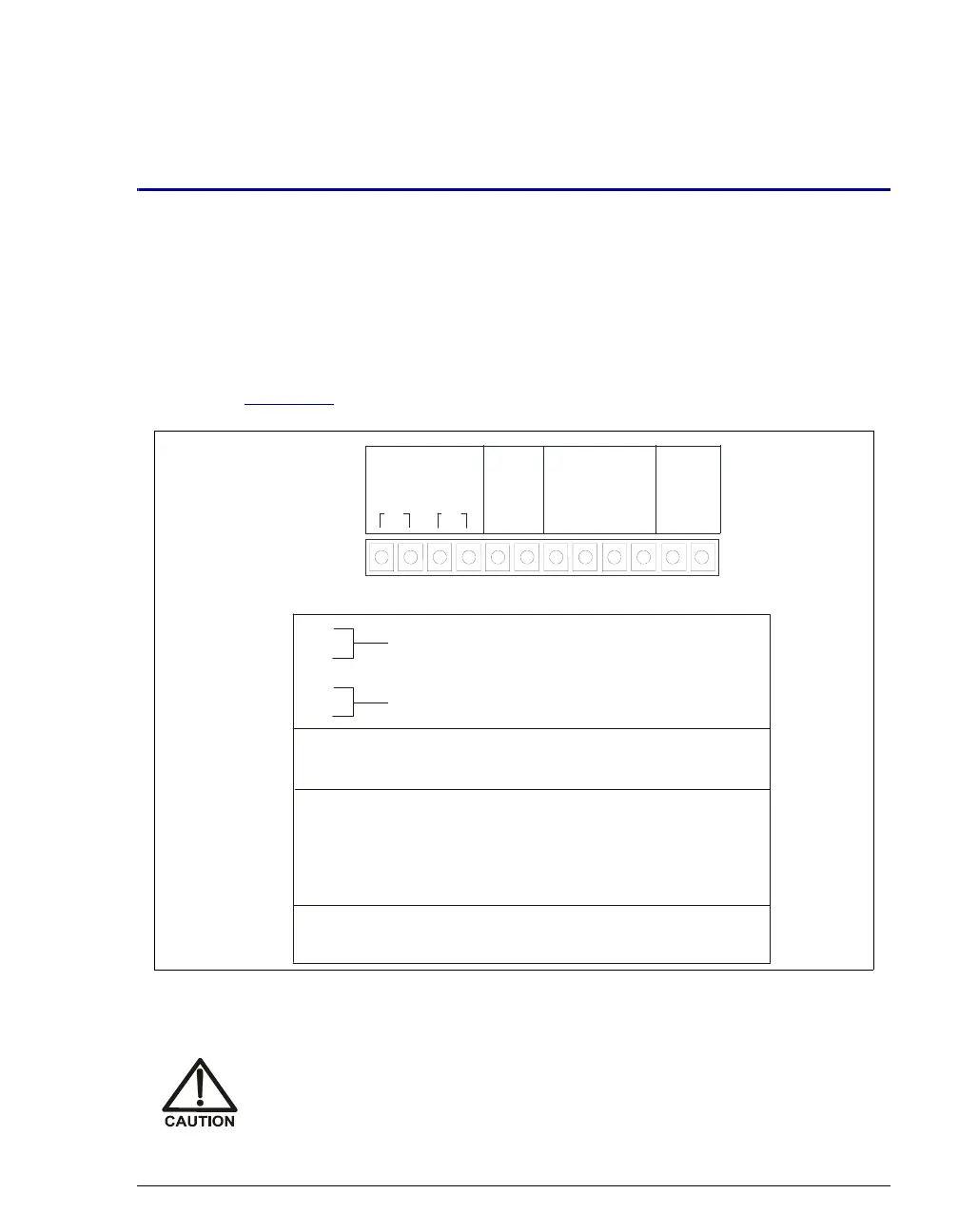
A 12-pin connector strip for TTL/relay control is located on the AS rear panel.
The connector provides two relay outputs, two TTL outputs, and four TTL inputs
(see Figure E-1
).
Figure E-1. TTL and Relay Connector on Rear Panel
Relay loads in excess of 200 mA or with included power supplies over
60 V may damage the relay drivers on the CPU.
12
3
4
56
7
8910
11 12
(+)
TTL OUT TTL GND
(-)
TTL IN
(+)
12 121
234
1
Pin Function
Connector Position
1
2
Solid State Relay Contacts Output
3
4
Solid State Relay Contacts Output
TTL Output 1 (1 k pull up to +5, 100 mA sink)
Ω
5
TTL Output 2 (1 k pull up to +5, 100 mA sink)
Ω
6
7
8
9
10
11
12
Ground
Ground
TTL Input 2 — Start/Continue Schedule
TTL Input 3 — Tray Temperature ON/OFF
TTL Input 4 — (not used)
TTL Input 1 — (not used)
2
OUT
RELAY