E • TTL and Relay Control
Doc. 065051-03 1/08 319
d. Connect the wires from the AS connector plug to the TTL or
relay connector pins on the other module(s). Additional connector
plugs are provided with other Dionex modules.
NOTE Check the polarity of each connection. Connect signal
wires to signal (+) pins and ground wires to ground (-)
pins.
E.1.2 Selecting TTL Input Control Types
The AS TTL inputs respond to four types of signals to accommodate
different controlling devices. The default control type,
Normal Edge, is
compatible with the output signals provided by Dionex modules.
If the device connected to the AS does not send a normal edge signal,
select the appropriate control type. Refer to the documentation provided
with the controlling device and the information below to select the correct
type. Select a different control mode from the
TIME FUNCTION IN screen
(see Figure E-3
).
Figure E-3. Time Function In Screen–Selecting Signal Modes
TTL Input Control Types
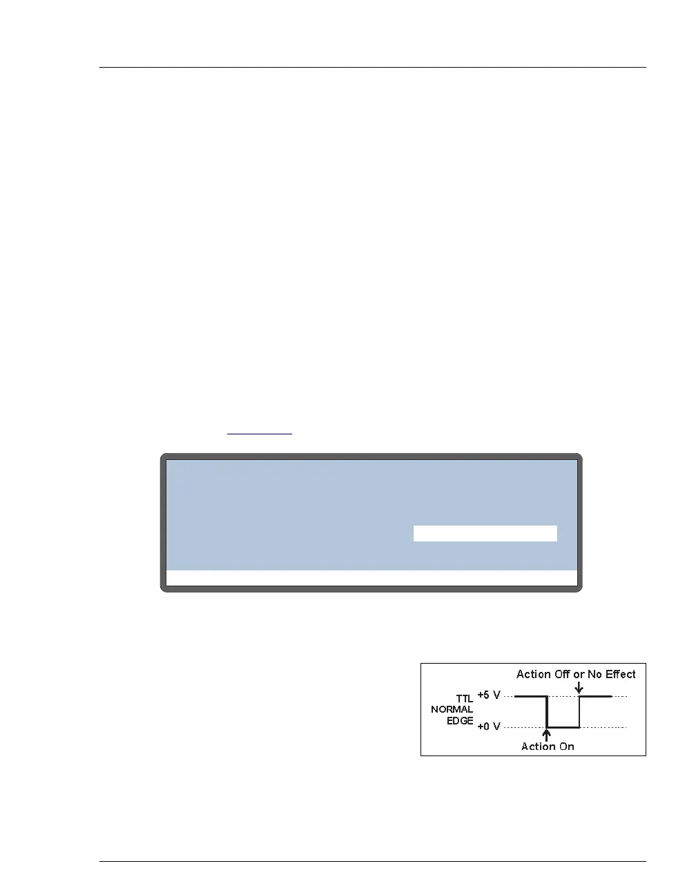
• Normal Edge: In normal edge
operation, the negative (falling)
edge of a signal turns on the
function. For example, for the
START-CONTINUE function, the
negative edge starts the
schedule (if it is not currently running), or continues the current
schedule if it is on hold.
Help Prompt
TIME FUNCTION IN
TTL MODE
1
2
3
START-CONTINUE:
TRAY TEMP ON/OFF:
NORMAL EDGE
UNUSED:
4
UNUSED: