AS Autosampler Operator’s Manual
318 Doc. 065051-03 1/08
The outputs can be used to control functions in external devices such as a Dionex
IC system module. When connected to a controlling device, the inputs can be
programmed to perform the following AS functions:
• Start and continue a schedule
• Turn the sample (tray) temperature control option on/off
Relay outputs 1 and 2 can be programmed to switch any low-voltage control.
Switched current must be less than 200 mA and 42 V peak.
E.1.1 Connecting a TTL or Relay
1. Locate the twisted
pair of wires
(P/N 043598) and
the 12-position
connector plug
(P/N 923686) (see
Figure E-2
) in the
AS Ship Kit
(P/N 062380 or
P/N 062381).
2. Follow these basic steps to connect the TTL or relays.
a. For each relay or TTL to be used, connect an active wire (red)
and a ground wire (black) to the 12-position connector plug at the
appropriate pin locations. Refer to Figure E-1
or the label on the
AS rear panel for the connector pin assignments.
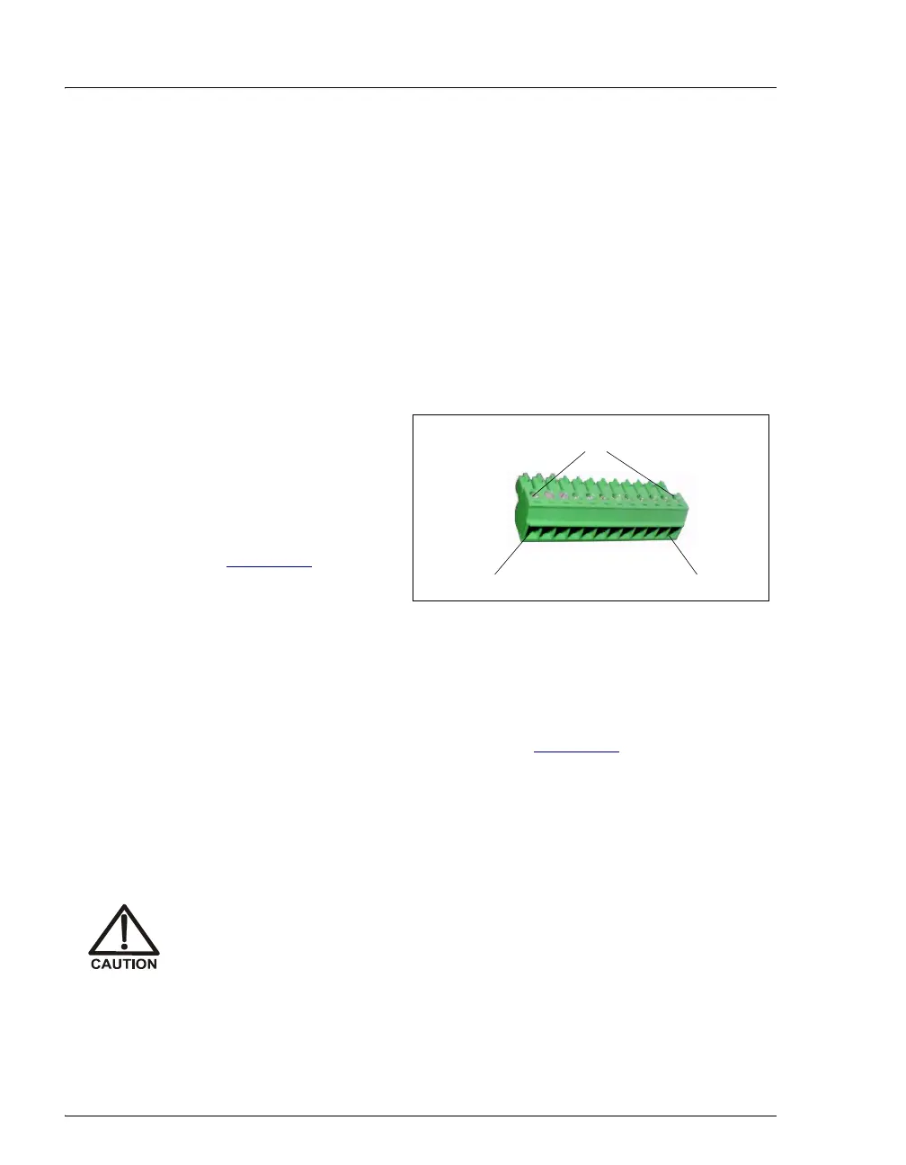
b. To attach a wire to the plug, strip the end of the wire, insert it into
the plug, and use a screwdriver to tighten the locking screw. If
necessary, multiple ground wires can be attached to a single TTL
input/output ground pin.
c. Plug the connector into the 12-pin connector on the AS rear
panel.
When attaching wires to the connector plug, be careful not to allow
stray strands of wire to short to the adjoining position on the
connector.
Figure E-2. 12-Position Connector Plug
Position 1
Position 12
Locking Screws