2 • Description
Doc. 065051-03 1/08 21
• The AS automatically detects the type of tray installed.
2.3.6 Injection Valve Options
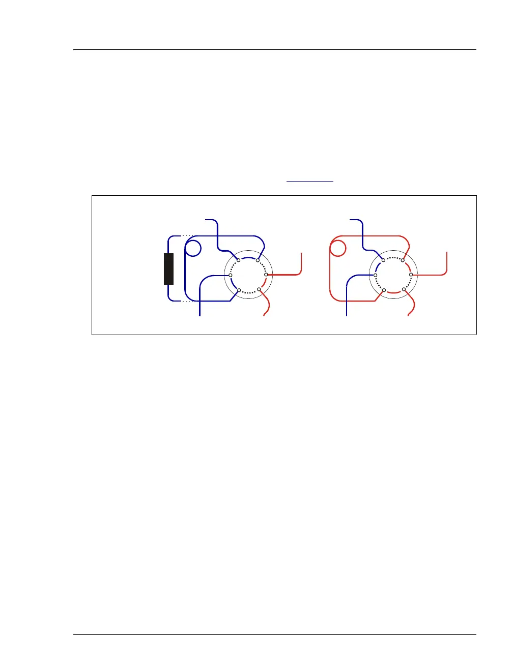
The AS can optionally have one or two injection valves installed inside
the autosampler compartment. The injection valves are six-port,
electrically-activated Rheodyne valves. The valves have two operating
positions: Load and Inject (see Figure 2-8
).
Eluent flows through either the Load or Inject path, depending on the valve
position:
• In the Load position, sample flows from the AS inject port line, through the
valve, and into the sample loop, where it is held until injection. Eluent flows
from the pump, through the valve, and to the column, bypassing the sample
loop. Excess sample flows out to waste.
• In the Inject position, sample is swept to the column for analysis. Eluent flows
from the pump, through the sample loop, and on to the column, carrying the
contents of the sample loop with it.
Figure 2-8. Injection Valve Flow Schematics
(1)
L
P
(2)
C
(3)
L
(4)
(5)
S
(6)
W
To Wa st e
Sample In
To C ol um n
From Pump
Sample
Loop
L
AD P
ITI
N
To Wa st e
Sample In
From Pump
Sample
Loop
INJE
T P
ITI
N
To C olu m
Concentrator
Column
(optional—
replaces loop)
(1)
L
P
(2)
C
(3)
L
(4)
(5)
S
(6)
W