E • TTL and Relay Control
Doc. 065051-03 1/08 321
E.2 Controlling TTL and Relay Outputs
The AS provides two TTL outputs and two relay contacts for control of functions
in external devices, such as an integrator. The relay outputs can be used to switch
any low-voltage control. Switched current must be less than 200 mA and 60 V
peak blocking. The relay-contact closures are normally open. When the relay is
closed, current flows to the connected device.
The TTL outputs are normally at 5 volts. Setting a TTL output to 0 volts turns on
the action in the connected device.
After connecting the TTL and Relay outputs (see Section E.1
), turn on and off the
output states in Direct Control from the
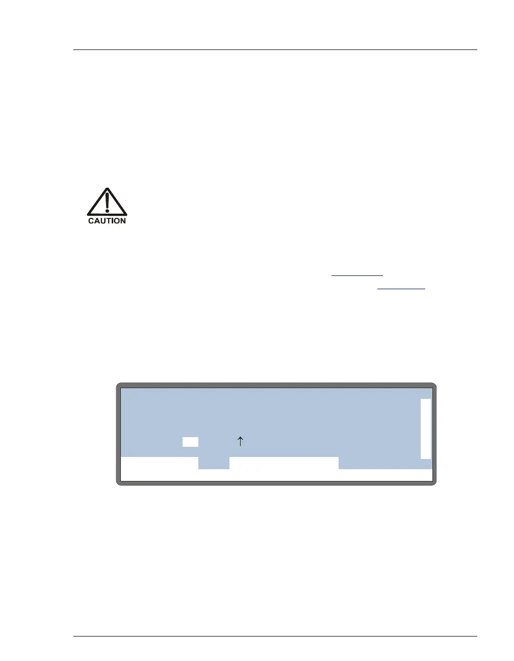
DETAIL screen (see Figure E-4), or in
Schedule Control during the timed events portion of the method. You can also use
Chromeleon or Chromeleon Xpress to control the outputs.
• To turn on a TTL or relay output, set the corresponding output field on the
DETAIL screen or method TIMED EVENTS screen to 1 (on).
• To turn off a TTL or relay output, set the corresponding output field to 0 (off).
Figure E-4. Detail Status Screen - Direct Control of TTL and Relays
Relay loads in excess of 200 mA or with included power supplies over
60 V may damage the relay drivers on the CPU.
Help Prompt
IDLE
VIAL#:
TIME:
INJ#:
VOL:
METHOD:
TRAY:
TRAY:
LOOP:
20 °C
25
100
2mL
uL
uL
min
TTL1
TTL2
RLY1
RLY2
0
1
0
0
LOCAL
DETAIL
DIRECT CONTROL
INJ VLV L
NORMAL FULL