Programming and operating manual Model 1001 DFB
102 FICEP S.p.A.
CHAPTER 10: MAINTENANCE AND TROUBLE SHOOTING
Signalling and messages
The CNCC: software is enabled to recognize some events giving out clearly messages for the operator;
depending on seriousness and danger of the situation, the CNC can “decide” to halt its working. Each
message is marked by a numerical code (error code) possibly followed by a second numerical code
(cause code); the two codes are separated by a “:” they appear in four different colours:
Information message
(Yellow)
An alarm shuts off the pow-
er to auxiliary circuits of the
machine leaving connected
only the CNC The action is
the same of the emergency
push-button.
A red message normally
occurs when something
dangerous happens, like a
collision, a damaged driver,
the emergency push-button
activated, etc…
F.I. “Encoder signals alarm
axis n”
A message informs the
operator about a par-
ticular condition of the
line; the CNC software
stops the actual action
but doesn’t shut off the
power.
F.I. “Enable for axis n
movement not
present”
A wait message in-
forms that the CNC
software asks for time
to end some opera-
tions, during which it
can’t accept orders
from operator.
F.I. “Waiting for end
of phase n. 2 of
zero cycle”
An error message
normally occurs when
a particular action or a
set up by operator is
wrong.
F.I. “Selection not
possible”
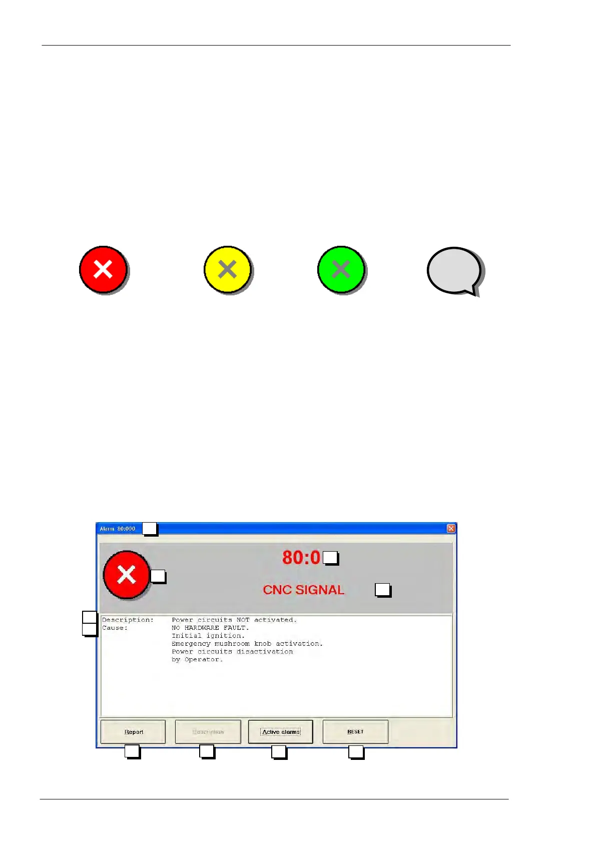
The window of a message is like in the following picture: