Model 1001 DFB Programming and operating manual
FICEP S.p.A. 13
CNC controlled positioning
Introduction
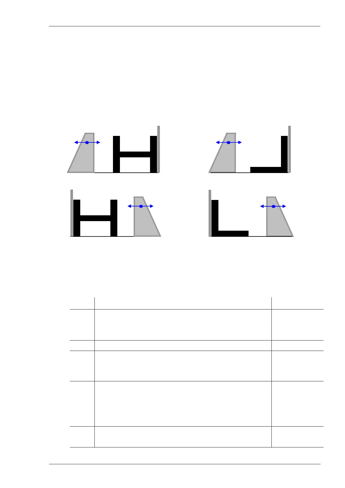
1. In this manual the expressions “side A”, “side B”, “side C” and “side D” are often used; these expres-
sions refer to the profile sides as shown in the following pictures. Note that the “A” refers always to the
profile side on the datum line of the machine, “B” to the mobile vice reference, “C” to upper side and
“D” to lower side of the profile.
The pictures on the left are applicable for each type of profiles except angles; while those on the right
are valid only for angles.
2. In this manual, we call “axes” all the CNC automatic controlled movements.
Axes table
Carriage axis for longitudinal positioning of material
Pincher positioning axis to suit profiles height (optional)
Magnet positioning axis for transferring of cut pieces (optional)
Traverse axis for the horizontal positioning of the drilling unit 1
Drilling
operations
(standard head)
Traverse axis for the vertical positioning of the drilling unit 1
Spindle rotation axis (stationary vice side)
Traverse axis for the horizontal positioning of the drilling unit 2 (op-
tional)
Drilling opera-
tions (second op-
tional head)
Traverse axis for the vertical positioning of the drilling unit 2 (op-
tional)
Spindle rotation axis (mobile vice side) (optional)
Probe axis on the stationary vice side (optional)
Probe axis on the mobile vice side (optional)