Model 1001 DFB Programming and operating manual
FICEP S.p.A. 11
CHAPTER 1: SYSTEM DESCRIPTION
Introduction of the system
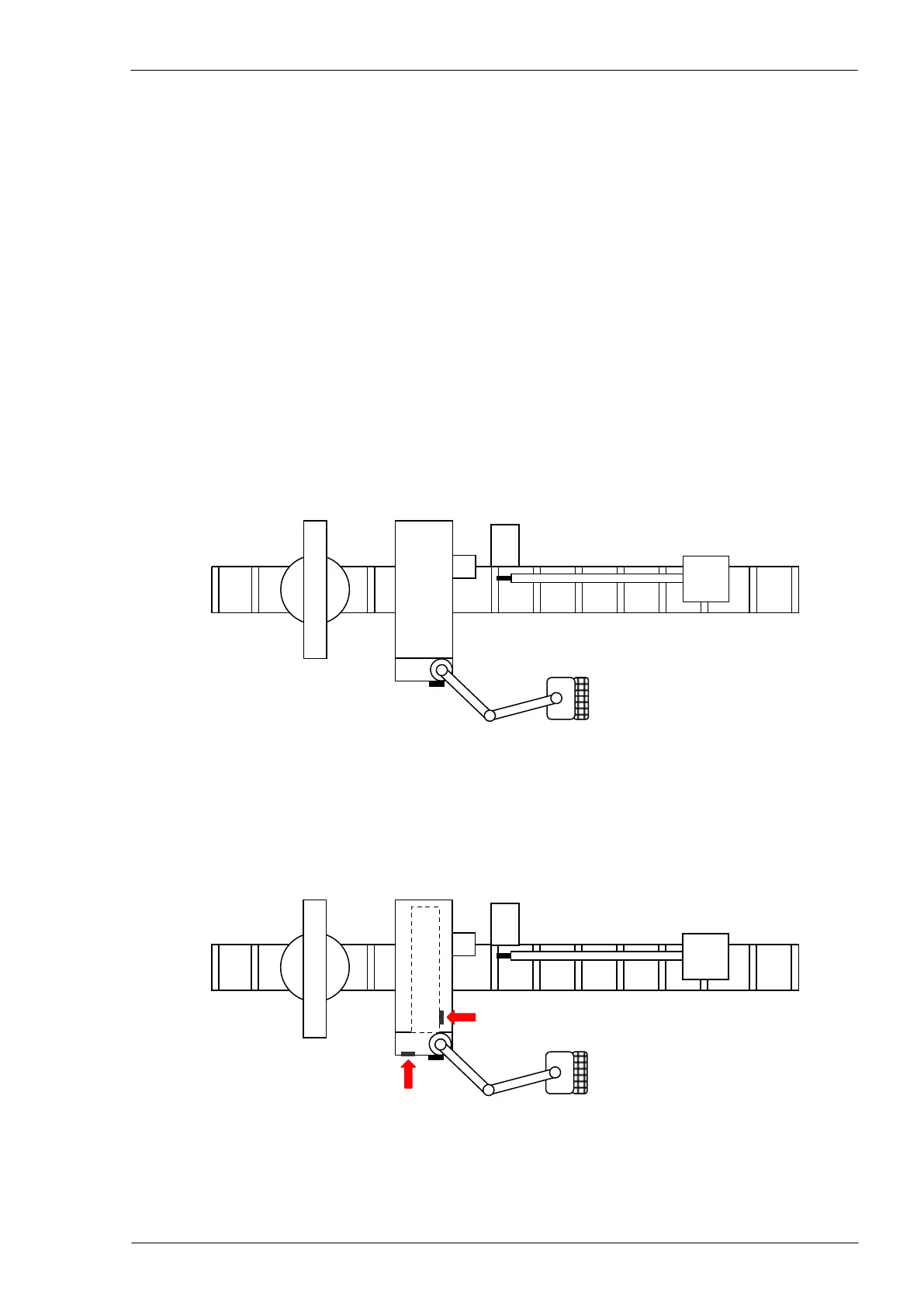
Possible layout of a standard system
The standard system is complete with:
1) rollers (loading side)
2) carriage
3) pincher
4) drilling unit
5) drilling head
6) cutting unit (saw)
7) marking unit (optional)
8) main switch
9) articulated arm
10) CNC and Operator’s position
11) rollers (unloading side)
Identification of the machine plates position
The plate with rating data is near the main electric switch while the plate with machine identification data is
fixed on the machine left lower corner, looking the machine from the loading (carriage) side.