Model 1001 DFB Programming and operating manual
FICEP S.p.A. 103
1) identification of the error on the window title bar
2) icon of the type of error; note that it could be in different colours
3) error code and, maybe, cause code
4) clearly type of signalling
5) clearly description of the problem
6) clearly description of the cause(s)
7) list of previous alarms
8) come back to the description window of current alarm
9) summarizing windows with the list of all active signalling
10) push-button to clear the active signalling; no effect if the cause of the problem is still active
N.B. Signalling on the gray part of the window (02, 03 e 04) are available on the lower part of all win-
dows too.
Sometimes it could happen that the signalling window is not foreground but under some other
open window; in this case the operator can press “ALT” + “H” keys of the PC keyboard; for
the alarm list, see “Appendix A”.
Display of Input/Output (I/O) condition
The CNC software allows to display the condition of all digital and analogue input-output signals to check
the right operation of all sensors and actuators.
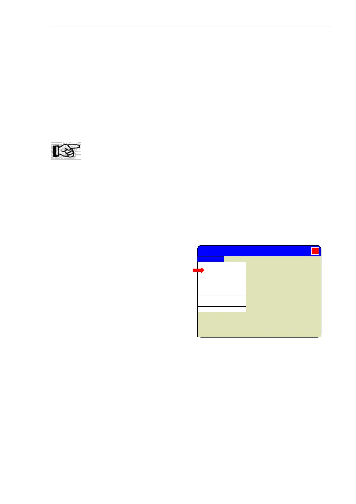
To display the condition of all I/O signals (called
“Channels” choose “View” “Channels” command
in the “Execution” window.
After the command the window changes displaying
the I/O condition instead of axes coordinates
Mitrol MINOSSE - Execution
Axes coordinates
Channels
Synoptic
Comment
Double canonic
Debug
Can. 1 activated
Can. 2 activated
Alarm/messages